NXTII spec.pdf - 第24页
Machine S tructure Edition 2.0E - 24 - NXT II S pecifications 4.7. Nozzles, Claws, and Needles 4 .7.1. Nozzle and Claw T ypes The H12HS [H12S], H08, H04/G04, H0 2 and H01 heads hold 1 2, 8, 4, 2 and 1 nozzles respectiv…
Machine Structure
Edition 2.0E - 23 - NXT II Specifications
4.6. Mark Camera Unit
Camera units attached to each head are used to process the PCB fiducial marks
in order to compensate for things such as PCB misalignment and warpage by
offsetting the part placing position.
Furthermore, PCB type recognition is achieved by reading a 2D code (Optional
Fujitrax function)
Field of View 9.1 mm × 9.1 mm
Fiducial mark size
Min. φ 0.5 mm ~
(Further specifications are identical to fiducial mark
cameras employed on previous machines.)
Note: Only circle mark, min 0.2mm ~.
Furthermore, it is possible to use through holes or land marks as fiducial marks
provided that the following conditions are satisfied.
• The shapes of the through holes or land marks are the same as standard
Fuji mark shapes.
• The through hole or land mark size is 3.5 mm or less.
• No other marks with the same shape exist within the field of view.
• The difference in contrast between the background and marks is 100 or
more.
• There is no dirt or scratches around the through hole or land mark
periphery.
• There is no unevenness at the edge of the through holes or land marks.
Machine Structure
Edition 2.0E - 24 - NXT II Specifications
4.7. Nozzles, Claws, and Needles
4.7.1. Nozzle and Claw Types
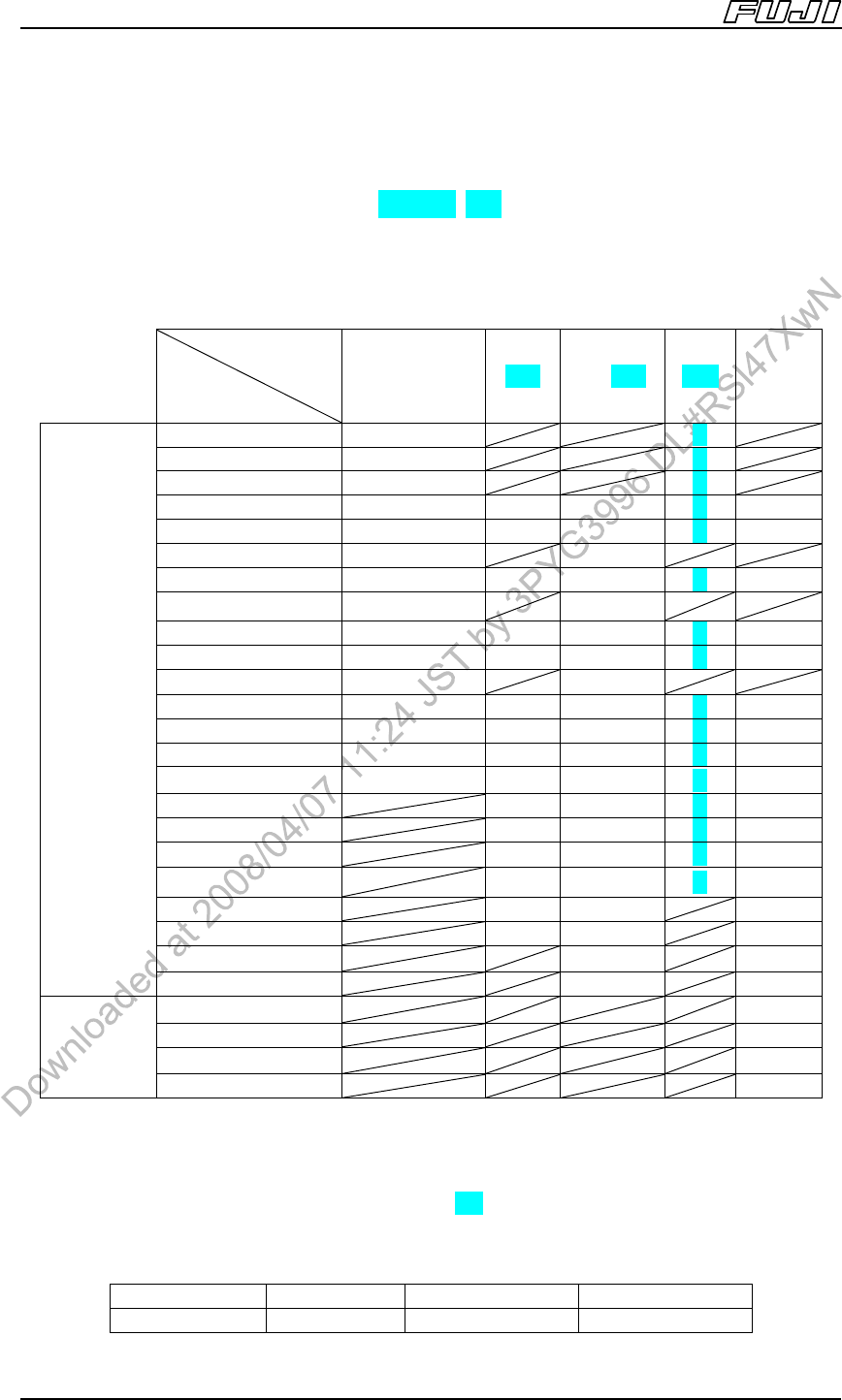
The H12HS [H12S], H08, H04/G04, H02 and H01 heads hold 12, 8, 4, 2 and 1
nozzles respectively, and the OF head holds 1 nozzle or claw. Supported
nozzles for each head are listed in the table below.
Placement
head
Head type
Note 1
H12HS
[H12S] /H08
Note 2
H04 H01,H02 G04 OF
φ0.3 O O
φ0.4 O O
φ0.7 O O
φ1.0 O O O
Note 3
O O
φ1.3 O O O O O
φ1.3M O O
φ1.8 O O O O O
φ1.8M O O
φ2.5 O O O O O
φ2.5G O O O O O
φ2.5M O O
φ3.7 O O O O O
φ3.7G O O O O O
φ5.0 O O O O O
φ5.0G O O O O O
φ7.0 O O O O
φ7.0G O O O O
φ10.0 O O O O
φ10.0G O O O O
φ15.0 O O O
φ15.0G O O O
φ20.0 O O
Nozzle
φ20.0G O O
1-A-14-4 O
1-A-14-10 O
1-A-14-30 O
Claw
Note 4,
5
1-A-14-60 O
Note:
1. The “G” suffix on the end of the nozzle size indicates nozzles fitted with a rubber pad. The “M” suffix on the
end of the nozzle size indicates nozzles designed for MELF parts.
2. The H12HS [H12S] and H08 heads use the same nozzles.
3. The premounted-part height when using the H01 or H02 head 1.0 mm nozzle is limited to 24.4 mm (Standard
specification: 25.4 mm).
4. The above listed claws for the OF head clasp the outside edges of all parts.
5. Supported part sizes for the above listed claws are as follows.
Tool No. Part width Part height Part length
1-A-14-4 1 ≤ W ≤ 31 3.5 ≤ H ≤ 25.4 4 < L ≤ 10
Machine Structure
Edition 2.0E - 25 - NXT II Specifications
1-A-14-10 10 < L ≤ 30
1-A-14-30 30 < L ≤ 60
1-A-14-60 60 < L ≤ 105
Note:
• The standard nozzle and claw set for the OF head contains 3 nozzle types (5.0G, 7.0G, 10.0G) and the 4
claw types listed above.
• A field with a slash indicates that a nozzle cannot be set.
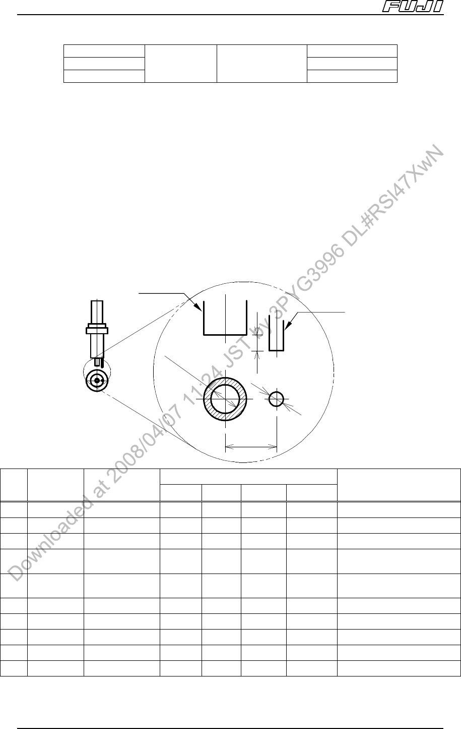
4.7.2. Needle Types
Only single needles are supported by the GL head.
A needle (inner diameter of φ0.58 mm) is attached as a standard accessory for
the GL head. Other needles can be purchased separately.
Note: The last digits of the drawing numbers (“**” shown in the table below) are changed each time
the design is changed.
Dimensions of each part
No.
Drawing Type
a b c d
Applicable Parts
1 AA5CT** φ1.0 Single φ1.0 φ0.5 1.8 mm 0.55 mm Large parts
2 AA3MC** φ0.9 Single φ0.9 φ0.5 1.7 mm 0.50 mm Medium to large parts
3 AA5CW** φ0.8 Single φ0.8 φ0.5 1.6 mm 0.45 mm Medium parts
4 AA3CR** φ0.7 Single φ0.72 φ0.7 1.5 mm 0.40 mm
General parts
excluding small chips
5 AA35N** φ0.6 Single φ0.58 φ0.7 1.5 mm 0.30 mm
General parts
excluding small chips
6 AA3MB** φ0.5 Single φ0.51 φ0.7 1.2 mm 0.25 mm 2125, 3216, SMIN, MIN
7 AA3MA** φ0.4 Single φ0.41 φ0.7 1.0 mm 0.20 mm 1608~3216, SMIN, MIN
8 AA3LZ** φ0.33 Single φ0.33 φ0.7 0.9 mm 0.15 mm 1608
9 AA3LY** φ0.3 Single φ0.30 φ0.7 0.9 mm 0.10 mm 1005, 1608
10 AA3LX** φ0.26 Single φ0.26 φ0.7 0.9 mm 0.10 mm 1005
Sto
pp
e
r
Needle
Ste
p
: d
Distance: c
Needle
Inner Dia.: a
Stopper
Outer dia.: b