NXTII spec.pdf - 第17页
Machine Specifications Edition 2.0E - 17 - NXT II S pecifications 3.6. PCBs Items Specifications M3II, M6II Min. 48(L) x 48(W) ~ Max. 534(L) x 510(W) (Us ing doubl e conveyor ) Min. 48(L) x 48(W) ~ Max. 534(L) x 610(W) (…
Machine Specifications
Edition 2.0E - 16 - NXT II Specifications
3.5. PCB Conveyance
Items Specifications
PCB flow direction Left -> right, right -> left
Conveyance height
900 (+15, -5) mm (950 (+15, -5) mm)
The conveyance height is specified when placing a
machine order.
Conveyance method Belt conveyance
Double conveyor 0 sec. during continuous operation
Note 1
M3II single conveyor
2.5 sec. (Conveyance time between modules when using
only M3II modules)
Note 2
Loading
time
M6II, M6IISP single conveyor
3.4 sec. (Conveyance time between modules when using
only M6II, M6IISP modules)
Note 2
Maximum load 1.5 kg (Up to a max. of 3 kg when using roller conveyor.)
Conveyor width change
Fixed front reference rail with motor assisted adjustable
side.
Notes:
1. 0 sec. not achievable when using PCB stopping position compensation function.
2. Time based on measurements under conditions performed at Fuji.
Machine Specifications
Edition 2.0E - 17 - NXT II Specifications
3.6. PCBs
Items Specifications
M3II, M6II
Min. 48(L) x 48(W) ~ Max. 534(L) x 510(W) (Using double conveyor)
Min. 48(L) x 48(W) ~ Max. 534(L) x 610(W) (Using single conveyor)
M6IISP
Min. 48(L) x 48(W) ~ Max. 520(L) x 510(W) (Using double conveyor)
Min. 48(L) x 48(W) ~ Max. 520(L) x 610(W) (Using single conveyor)
Thickness: 0.4 ~ 6 mm (Consult Fuji regarding the use of PCBs with thickness
less than 0.4 mm)
PCB size
Notes:
1. Double conveyors can handle PCBs up to 280(W) mm. PCBs larger than
280(W) mm must be produced by changing the double conveyor to single lane
production mode.
2. PCBs with 0.3 ~ 0.4 mm in thickness are supported as an option.
3. When using PCBs larger than 250(L) mm on M3II modules, paired module
production is performed. (Refer to section 6.2)
Furthermore, the placement area on M3II modules extends up to 250(L) mm,
however, it is possible to convey PCBs up to 305(L) mm. In a situation such as
this, it is necessary to perform placement for the section lying outside the
250(L) mm area using an M6II, M6IISP module, or by performing M3II paired
module production. Fiducial marks must be within the range of 250(L) mm.
4. The following limitations apply to the panel size when using the G04 head.
M3II module: Max. 214(L) mm, M6II module: Max. 504(L) mm
M6IISP module: Max 490(L) mm
5. The G04 head is not supported for paired module production.
6. Consult with Fuji in advance regarding PCB support measures.
Materials
Glass-epoxy, composite, paper phenol, alumina, polyimide, etc.
(Please consult with Fuji regarding support for ceramic PCBs)
Machine Specifications
Edition 2.0E - 18 - NXT II Specifications
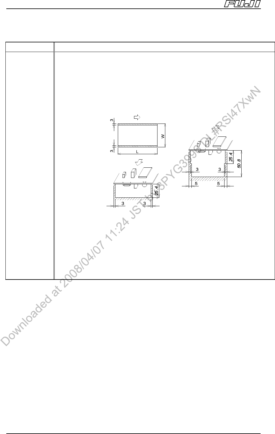
Items Specifications
PCB conditions Warpage: Max. 2.0 mm
If downward PCB warpage occurs when the PCB is clamped, please use back-up
pins or a back-up plate to support the underside of the PCB.
Premounted part height: Differs depending on the head types (refer to “3.4 Head
Specifications”).
Premounted part height on lower surface: Max. 25.4 mm.
• No premounted parts possible in the shaded areas.
• 3 mm of dead space on both edges of the PCB is required for clamping.
• Contact Fuji if the PCB warpage is lower than the conveyance surface.
• It is necessary that 50% of the contact surface on the underside of the panel
indicated above be touching the conveyor surface. Furthermore, contact Fuji if
there are notches at both sides of the PCB and the PCB warpage is lower than
the conveyance surface.
<When using back-up pins>
< Without back-up pins>
<Bottom surface>
<Top surface>
* Without back-up pins: Max =
50.8mm.