NXTII spec.pdf - 第9页
Machine Specifications Edition 2.0E - 9 - NXT II S pecifications 3. Machine S pecifications 3.1. Machine S pecification s Items Specification Part size (0402 Note 2 ) 0603 ~ 74 × 74 mm (32 × 180 mm) Parts Note 1 Max. par…
Machine Data and Operating Environment
Edition 2.0E - 8 - NXT II Specifications
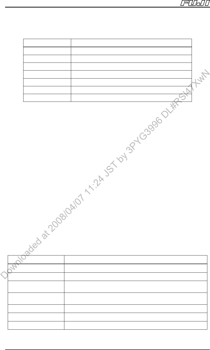
Power Consumption
Type
Estimated maximum power consumption (kVA)
M3II module 1.5
M6II module 1.5
M6IISP module 1.2
4MII base 1.0
2MII base 1.0
Tray unit-L 0.1
Tray unit-LT 0.5
Note: Values change depending on the conditions used.
* Cautions when installing NXTII
The following cautions should be observed when installing the NXTII:
1. A dedicated power source, not shared with other large equipment, should be
used in order to avoid problems with electrical noise, voltage fluctuations,
high-frequency distortions, and other related problems.
2. There is leakage current of approximately 30 mA per one NXTII machine
(one 4MII base with 4 M3II modules). It may be required to consider the
limitation for the number of machines that are connected to a breaker when
using leak detectors. It is also required to install an isolating transformer to
the machine when needed to avoid this electric leakage. The user must
prepare the isolating transformer.
3. When using a short circuit breaker, ensure to use a high-speed model with
sensed current of 100 mA. Use one short circuit breaker for up to two 4MII
bases.
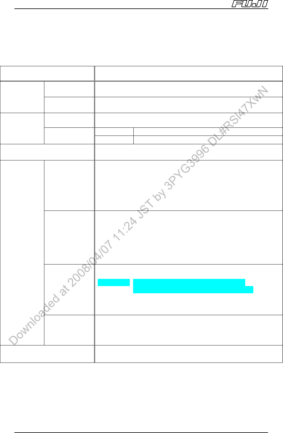
Recommended isolating transformer specifications
Items
Specifications
Phase
Three phase
Frequency
50/60Hz
Primary-side voltage
(input)
Depends on customer’s power supply devices
Secondary-side voltage
(output)
200V±10%
Power consumption Refer to the previous “Power Consumption” item
Note
Must be isolating transformer
Installation location Location in the vicinity of the machine (base) recommended
Machine Specifications
Edition 2.0E - 9 - NXT II Specifications
3. Machine Specifications
3.1. Machine Specifications
Items Specification
Part size (0402
Note 2
) 0603 ~ 74 × 74 mm (32 × 180 mm)
Parts
Note 1
Max. part height Max 25.4 mm
Chip and small
odd-form parts
±0.050 mm Cpk ≥1.00, ±0.066 mm Cpk ≥1.33
M3II, M6II ±0.030 mm Cpk ≥1.00, ±0.040 mm Cpk ≥1.33
Placing
accuracy
Note 3
Leaded parts
M6IISP ±0.018 mm Cpk ≥1.00, ±0.024 mm Cpk ≥1.33
Pick-up rate
Note 4
99.95% (not including automatic recovery)
Tape size
JEITA (formerly EIAJ), JIS standard tape parts
Concerning 8 mm tape with 7 inch reels, the reel width should be
14.0 mm or less.
8 mm tape: 13 inch reels or smaller
12 ~ 88 mm tape: 15 inch reels or smaller
Note: Please refer to “Device Unit Specifications Manual” for detailed
specifications.
Stick
Type S 4.5 ≤ part length ≤ 60 mm
Type L 60 ≤ part length ≤ 180 mm
Type 1 4 ≤ part width ≤ 15 mm (6 ≤ stick width ≤ 18 mm)
Type 2 15 ≤ part width ≤ 32 mm (18 ≤ stick width ≤ 36 mm)
Note: There are 4 types of stick feeders: 1S, 2S, 1L and 2L.
Note: Please refer to “Device Unit Specifications Manual” for detailed
specifications.
Tray size
Tray unit-L 335(W) x 330(L) mm (When 1 tray loaded)
160(W) x 330(L) mm (When 2 trays loaded)
Tray unit-LT 276(W) x 330(L) mm (When 1 tray loaded)
135.9(W) x 330(L) mm (When 2 trays loaded)
Tray unit-M 135.9(W) x 322.6(L) mm (JEDEC standard)
Note: Please refer to “Device Unit Specifications Manual” for detailed
specifications.
Packaging
Other
JIS, JEITA (formerly EIAJ) standard tape parts, stick parts, tray parts,
etc. (Parts supported by EIA standard also supported by JEITA
(formerly EIAJ)
Fiducial mark reading time
Note 5
Approximately 0.25 sec./mark
Notes:
1. Limitations apply based on the placing head used.
2. The following conditions are required when placing 0402 (01005) parts.
a. Manual offsetting using PAM is recommended when the required placement accuracy is ±0.05 mm or
less.
b. Changes to Fuji Flexa nozzle spec data are required.
c. 0402 (01005) compatible feeders are required.
Machine Specifications
Edition 2.0E - 10 - NXT II Specifications
3. The placing accuracy varies depending on the placing head used. The placing accuracy is obtained from
tests conducted by Fuji. Parts rotational offset is not considered. Also, the above placing accuracy may not
be obtained depending on the quality of the PCB and the parts that are placed.
4. Obtained from tests conducted by Fuji. Errors due to packaging are not included.
5. Obtained when reading a 1.2 mm diameter mark, excluding the time required to travel from mark to mark,
and to make adjustments for mark shape variations and location errors.