NXTII spec.pdf - 第22页
Machine S tructure Edition 2.0E - 22 - NXT II S pecifications Pin 4.5. Parts Camera Unit Each module is eq uipped with a fixed parts camera uni t which is used to acquire the part image and pe rform the necessary compe…
Machine Structure
Edition 2.0E - 21 - NXT II Specifications
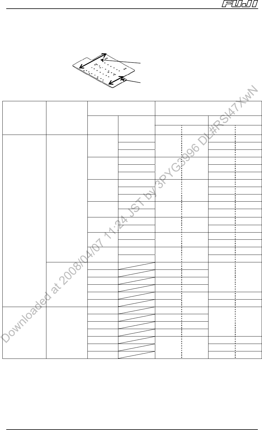
The back-up plate combinations when using automatic back-up pins for paired module
production (M3 (S) modules) are as follows.
PCB size (W) (mm)
Back-up Plate Size (W) (mm)
Note 5
and
Overhang part Y direction length (mm)
Lane 1 Lane 2
Conveyor
Specifications
PCB
Conveyance
Method
Lane 1 Lane 2
a b a b
48~120 312 27
120~200 312 105
48~120
200~280
312 27
312 185
48~120 312 27
120~200 312 105
120~200
200~280
312 105
312 185
48~120 312 27
120~200 312 105
200~280
200~280
312 185
312 185
48~120 215 27
48~120
120~165
215
Note 6
27
215 105
48~120 215 27
120~165
120~165
215
Note 6
105
215 105
48~120 250 27
48~120
120~200
250
Note 6
27
250 105
48~120 250 27
Double
conveyance
120~200
120~200
250
Note 6
105
250 105
48~120 312 27
120~200 312 105
200~280 312 185
280~360 312 260
312
Note 7
0
360~440 312 312 49.5
Double
conveyor
Single
conveyance
440~510 312
293.5
312 129.5
48~120 312 27
120~200 312 105
200~280 312 185
280~360 312 260
312 0
360~440 312 49.5
440~520 312 129.5
Single
conveyor
Single
conveyance
520~610
312 293.5
312 209.5
5. Each lane has its own respective back-up plate.
6. When using this back-up plate, the rear conveyor is adjusted to a position further forward from the standard
position (PCB width: 280 mm). As a result, when producing PCBs on the rear conveyor, the Y-axis
movement distance is shorter when compared with the movement distance when the rear conveyor is at its
standard position, therefore resulting in a faster cycle time.
7. The backup plate is identical to when not doing paired module production. Any other time, the backup plate
for paired module production is required.
Machine front
Machine rear
Overhang part (b)
Backu
p
p
late size
(
a
)
Machine Structure
Edition 2.0E - 22 - NXT II Specifications
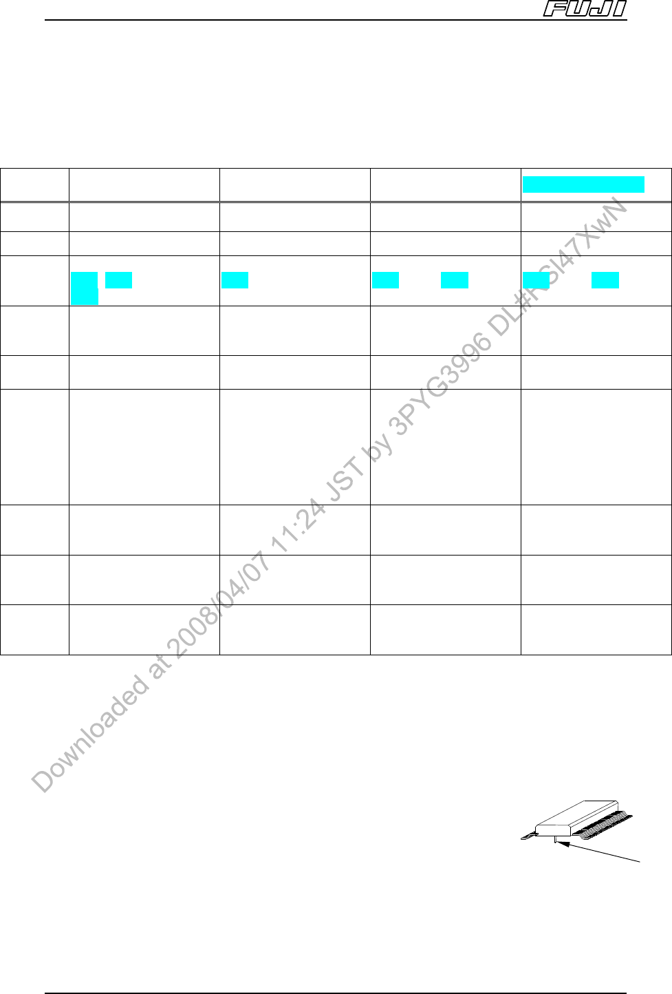
Pin
4.5. Parts Camera Unit
Each module is equipped with a fixed parts camera unit which is used to acquire
the part image and perform the necessary compensation for placement.
All parts are processed using frontlighting.
Standard Parts
Camera
Sidelight Parts
Camera
High Resolution
Parts
Camera
P03 Parts Camera
Lighting Frontlight Frontlight and sidelight Frontlight Frontlight
Module M3II, M6II, M6IISP M6II, M6IISP M3II, M6II, M6IISP M3II, M6II, M6IISP
Head
H12HS[H12S], H08,
H04, H02, H01
,
G04,OF
Note 5
H02, H01, OF only H02, H01, G04 only H02, H01, G04 only
Part size
(XY)
(0402 (01005))
0603 (0201) ~ 74 x 74
mm (32 x 180)
Note 1
1608 (0603) ~
35 x 35 mm (35 x 120)
Note 6
0402 ~ 9 x 9 mm 0402
~ 25 x
25mm
Note 7
Field of
view
52.1 mm×52.1 mm 52.1 mm×52.1 mm 15.4 mm×15.4 mm 38.6 mm×38.6 mm
Part
height
25.4 mm
25.4 mm
Note 2
6 mm or less for pins
and
other protrusions.
Note 3
Min. pin protrusion
from
underside of part
is 2 mm
Note 4
25.4 mm
2.5 mm
(
4 parts read at a time
)
6.5 mm
(
individually read
)
Min. pitch
Lead: 0.24 mm
Note 8
Bump: 0.40 mm
Note 8
Lead: 0.24 mm
Bump: 0.40 mm
Pin: 0.40 mm
Bump: 0.14 mm
Lead: 0.24 mm
Bump: 0.30 mm
Min.
diameter
Lead: 0.12 mm
Note 8
Bump: 0.25 mm
Note 8
Lead: 0.12 mm
Bump: 0.25 mm
Pin: 0.25 mm
Bump: 0.07 mm
Lead: 0.12 mm
Bump: 0.12 mm
Min. gap
Lead: 0.12 mm
Note 8
Bump: 0.15 mm
Note 8
Lead: 0.12 mm
Bump: 0.15 mm
Pin: 0.15 mm
Bump: 0.07 mm
Lead: 0.12 mm
Bump: 0.12 mm
1 Images for parts over 38 × 45 or 45 x 38mm in size are acquired using multiframe processing. Please refer to
P6 for details regarding the conditions for 0402 (01005) parts.
2. The stated height includes pins and other protrusions.
3. Limitations may apply depending on the type of unit mounted at the module.
4. A setting for specifying the minimum pin protrusion amount is available to account for the possibility of other
leads appearing in the image. The value stated above may vary depending on the color or material used for
the part underside.
5. It is only possible to use the OF head in NXT M6II, M6IISP modules.
6. Images for parts larger than 35 x 35 mm are acquired using multiframe processing.
7. The size of the parts that can be read four at a time by the G04 head must be 4 x 4
mm or smaller, with a part height of 2.5 mm or smaller.
8. The numerical value is a specification for the camera unit. The specification may
change according to the head combination. (For more information, refer to 3.4 Head
specifications.)

Machine Structure
Edition 2.0E - 23 - NXT II Specifications
4.6. Mark Camera Unit
Camera units attached to each head are used to process the PCB fiducial marks
in order to compensate for things such as PCB misalignment and warpage by
offsetting the part placing position.
Furthermore, PCB type recognition is achieved by reading a 2D code (Optional
Fujitrax function)
Field of View 9.1 mm × 9.1 mm
Fiducial mark size
Min. φ 0.5 mm ~
(Further specifications are identical to fiducial mark
cameras employed on previous machines.)
Note: Only circle mark, min 0.2mm ~.
Furthermore, it is possible to use through holes or land marks as fiducial marks
provided that the following conditions are satisfied.
• The shapes of the through holes or land marks are the same as standard
Fuji mark shapes.
• The through hole or land mark size is 3.5 mm or less.
• No other marks with the same shape exist within the field of view.
• The difference in contrast between the background and marks is 100 or
more.
• There is no dirt or scratches around the through hole or land mark
periphery.
• There is no unevenness at the edge of the through holes or land marks.