NXTII spec.pdf - 第16页
Machine Specifications Edition 2.0E - 16 - NXT II S pecifications 3.5. PCB Conveyance Items Specifications PCB flow direction Left -> right, right -> left Conveyance height 900 (+15, -5) mm (950 (+15, -5) mm) The c…
Machine Specifications
Edition 2.0E - 15 - NXT II Specifications
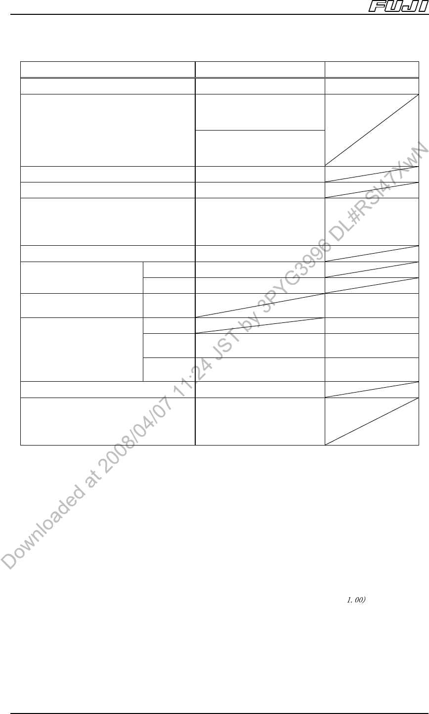
Items OF
Note 21
GL
Note 20
No. of nozzles/needles 1 nozzle or claw 1
<Standard camera>
Note 16
1608 (0603) ~ 74 x 74 mm
(32 x 180)
Part size
<Sidelight camera>
Note 16
1608 (0603) ~ 35 x 35 mm
(35 x 120)
Max. part height 25.4 mm (including leads)
Max. lead length 6.0 mm
Max. premounted part height
(upper surface)
Note 20
25.4 mm
0 mm (Z:4 mm)
0 mm (Z:6 mm)
3 mm (Z:8 mm)
7 mm (Z:12 mm)
Packaging Tape, Tray, Stick
Cpk≥1.00 ± 0.050
Note 19
Placing accurac
y
Note 13
(parts with leads)
Cpk≥1.33 ±0.066
Glue dispensing accuracy
Note 14
Cpk≥1.00 ±0.100
M3II 0.22 sec/dot
M6II
3000 (Frontlight/nozzle)
2500(Frontlight/claw)
same as above
Throughput
Note 15
CPH (chips/hr)
M6IISP
2800 (Frontlight/nozzle)
2000(Frontlight/claw)
same as above
Nozzle change Yes
Lead parts
Bump parts
Depends on the part
camera specification.
Refer to”4.5 Parts Camera
Unit”.
Notes:
13. The placement accuracy is based on tests conducted at Fuji.
14. The GL head dispensing accuracy is based on tests conducted at Fuji.
15. The throughput is based on tests conducted at Fuji.
16. The max. size of the short side of the part is 31 mm when using claws.
17. The glue temperature control function and application volume offset function are included with the GL head.
The optional units listed below are required when attaching the GL head.
a. Nozzle changer cover (for M3II or for M6II, M6IISP)
b. Parts camera cover
c. GCU (Glue Check Unit
18. OF head can be attached to M6II, M6IISP modules.
19. The placement accuracy with the nozzle after performing PAM is ± 0.030 mm (Cpk ≥ . The placement
accuracy, as well as note 15, is based on tests conducted at Fuji.
20. GL head premounted parts height differs depending on the Z axis stroke.
Machine Specifications
Edition 2.0E - 16 - NXT II Specifications
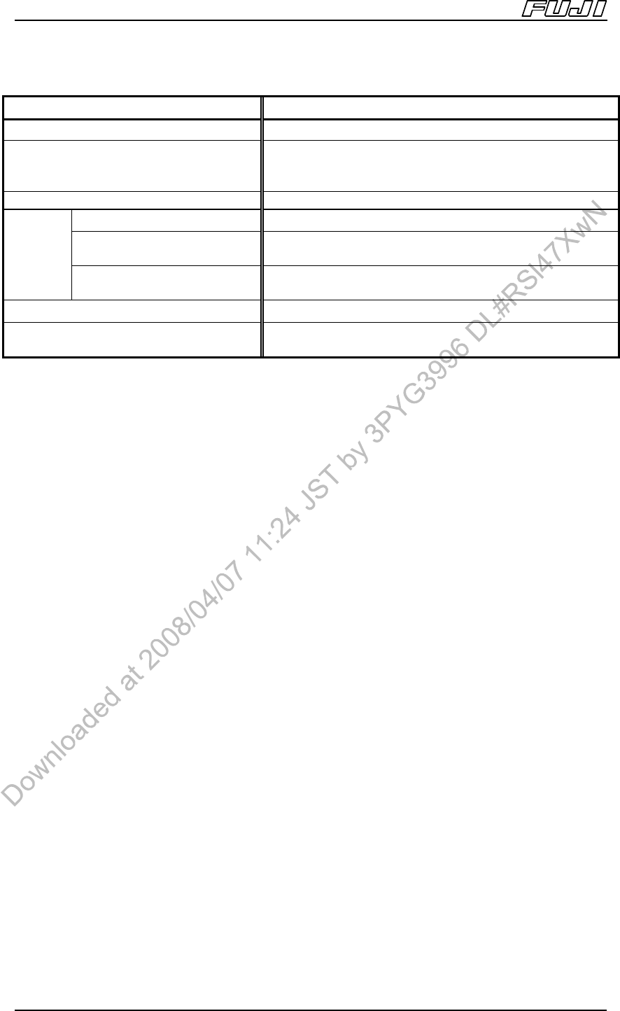
3.5. PCB Conveyance
Items Specifications
PCB flow direction Left -> right, right -> left
Conveyance height
900 (+15, -5) mm (950 (+15, -5) mm)
The conveyance height is specified when placing a
machine order.
Conveyance method Belt conveyance
Double conveyor 0 sec. during continuous operation
Note 1
M3II single conveyor
2.5 sec. (Conveyance time between modules when using
only M3II modules)
Note 2
Loading
time
M6II, M6IISP single conveyor
3.4 sec. (Conveyance time between modules when using
only M6II, M6IISP modules)
Note 2
Maximum load 1.5 kg (Up to a max. of 3 kg when using roller conveyor.)
Conveyor width change
Fixed front reference rail with motor assisted adjustable
side.
Notes:
1. 0 sec. not achievable when using PCB stopping position compensation function.
2. Time based on measurements under conditions performed at Fuji.
Machine Specifications
Edition 2.0E - 17 - NXT II Specifications
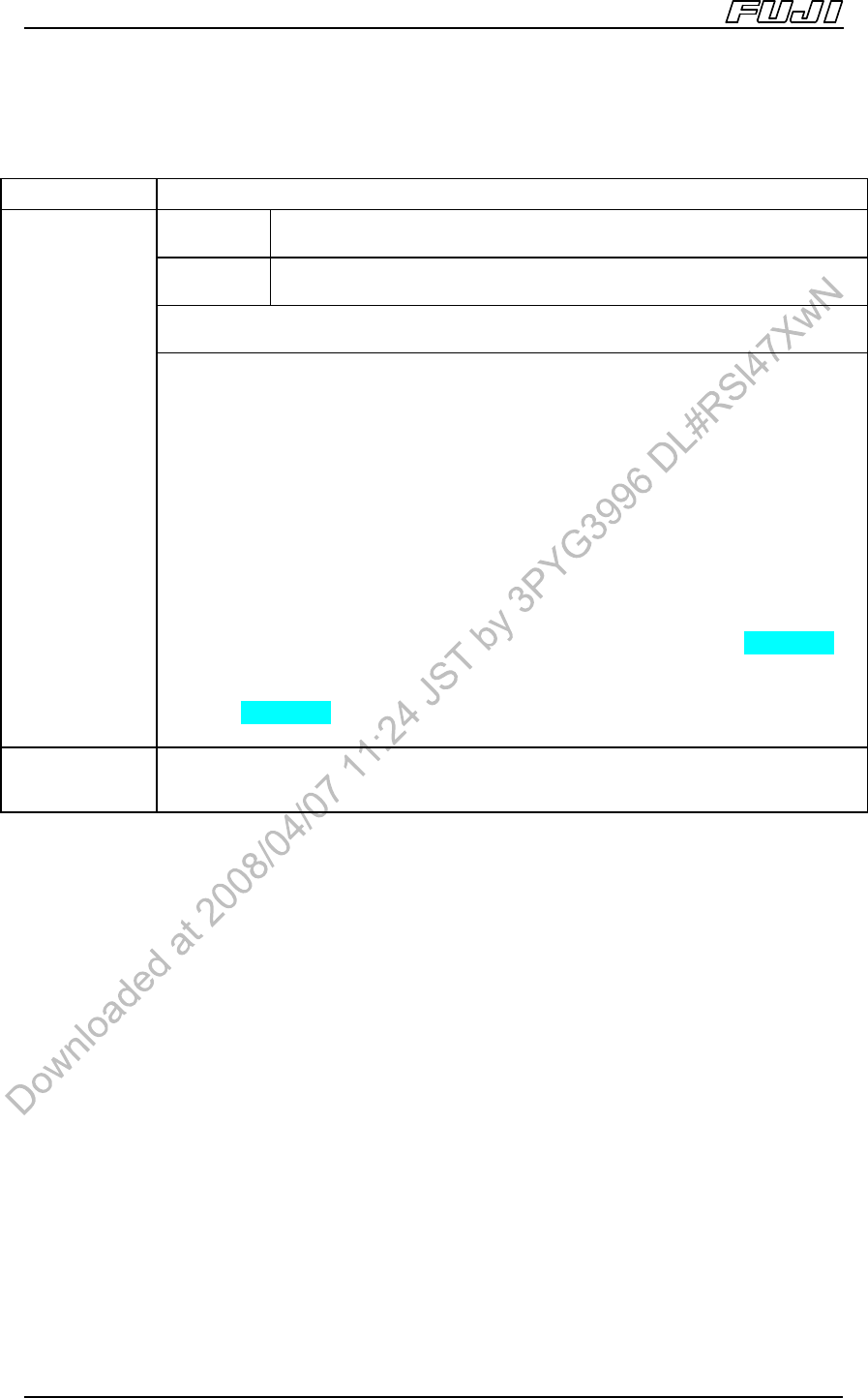
3.6. PCBs
Items Specifications
M3II, M6II
Min. 48(L) x 48(W) ~ Max. 534(L) x 510(W) (Using double conveyor)
Min. 48(L) x 48(W) ~ Max. 534(L) x 610(W) (Using single conveyor)
M6IISP
Min. 48(L) x 48(W) ~ Max. 520(L) x 510(W) (Using double conveyor)
Min. 48(L) x 48(W) ~ Max. 520(L) x 610(W) (Using single conveyor)
Thickness: 0.4 ~ 6 mm (Consult Fuji regarding the use of PCBs with thickness
less than 0.4 mm)
PCB size
Notes:
1. Double conveyors can handle PCBs up to 280(W) mm. PCBs larger than
280(W) mm must be produced by changing the double conveyor to single lane
production mode.
2. PCBs with 0.3 ~ 0.4 mm in thickness are supported as an option.
3. When using PCBs larger than 250(L) mm on M3II modules, paired module
production is performed. (Refer to section 6.2)
Furthermore, the placement area on M3II modules extends up to 250(L) mm,
however, it is possible to convey PCBs up to 305(L) mm. In a situation such as
this, it is necessary to perform placement for the section lying outside the
250(L) mm area using an M6II, M6IISP module, or by performing M3II paired
module production. Fiducial marks must be within the range of 250(L) mm.
4. The following limitations apply to the panel size when using the G04 head.
M3II module: Max. 214(L) mm, M6II module: Max. 504(L) mm
M6IISP module: Max 490(L) mm
5. The G04 head is not supported for paired module production.
6. Consult with Fuji in advance regarding PCB support measures.
Materials
Glass-epoxy, composite, paper phenol, alumina, polyimide, etc.
(Please consult with Fuji regarding support for ceramic PCBs)