NXTII spec.pdf - 第14页
Machine Specifications Edition 2.0E - 14 - NXT II S pecifications Lead parts Bump parts Depends on t he part camera specification. Refer to”4.5 Part s Camera Unit”. 7. The placing accuracy above i s based on tests conduc…
Machine Specifications
Edition 2.0E - 13 - NXT II Specifications
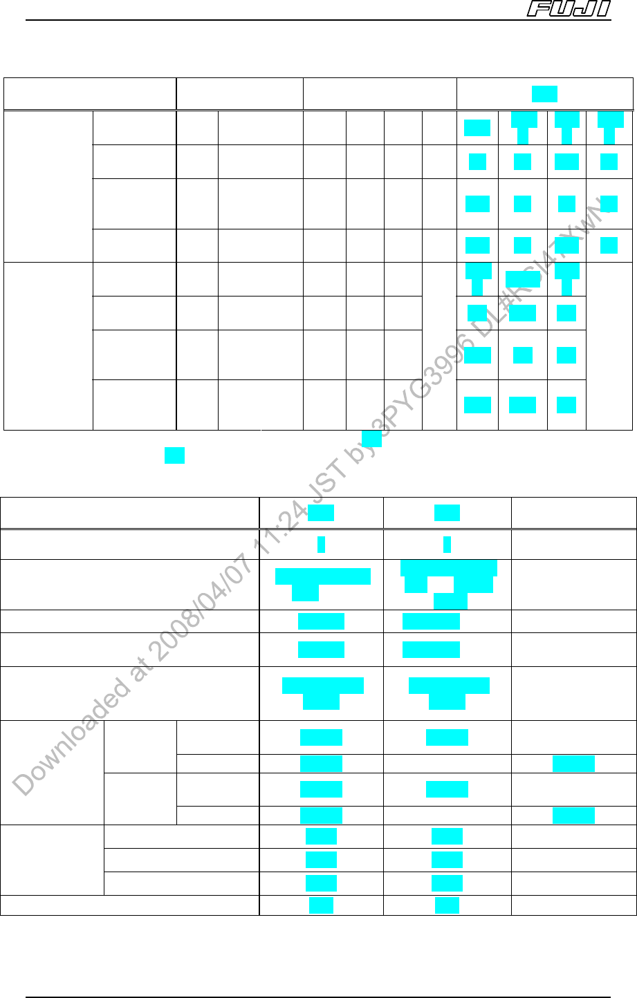
Items H12HS[H12S] H08 H04
Part size
~1.9 x
1.9
~2.8 x
2.8
~5 x 5
~2.4 x
2.4
~3.6x
3.6
~6.5x
6.5
~7.5
x 7.5
~9 x 9
~14 x
14
~26 x
26
~32 x
32
Min. pitch
(mm)
0.4 0.5 0.65 0.4 0.5 0.65 0.9
0.4 0.5 0.65 0.9
Min.
width/dia.
(mm)
0.17 0.2 0.3 0.17 0.2 0.3 0.4
0.17 0.2 0.3 0.4
Lead parts
Note 6
(Part size
includes leads)
Min. spacing
(mm)
0.23 0.3 0.35 0.23 0.3 0.35 0.5
0.23 0.3 0.35 0.5
Part size
~2.7 x
2.7
~3.8 x
3.8
~5 x 5
~3.4 x
3.4
~4.8
x 4.8
~7.5
x 7.5
~13 x
13
~19x 19
~32 x
32
Min. pitch
(mm)
0.5 0.65 0.5 0.5 0.65 1.0
0.5 0.65 1.0
Min.
width/dia.
(mm)
0.25 0.3 0.5 0.25 0.3 0.5
0.25 0.3 0.5
Bump parts
Note 6
Min. spacing
Between
bumps (mm)
0.25 0.35 0.5 0.25 0.35 0.5
0.25 0.35 0.5
6. The Bump parts specifications for H12S [H12], H08, and H04 heads, and the lead parts specifications for
H12S[H12]/H08/H04 heads will differ based on the part size. (Using the conditions for manual offsets based
on theoretical PAM.)
Items G04 H02 H01
No. of nozzles 4 2 1
Part size
0402 ~ 15 x 15
mm
Note 12
1608 ~ 74 × 74
mm
Note 9
(32 ×
180)
1608 ~ 74 × 74
mm (32 × 180)
Max. part height 6.5 mm 25.4 mm
Note 10
25.4 mm
Max. premounted part height (upper
surface)
6.5 mm 25.4 mm
Note 10
25.4 mm
Packaging
Tape, Trays,
Sticks
Tape, Trays,
Sticks
Tape, Trays,
Sticks
M3II, M6II
±0.030 ±0.030
± 0.030
± 0.050
Note 11
Cpk
≥
1.00
M6IISP
±0.018 ±0.018 ±0.018
M3II, M6II
±0.040 ±0.040
± 0.040
± 0.066
Note 11
Placing
accuracy
Note 7
(parts with leads)
Cpk
≥
1.33
M6IISP
±0.024 ±0.024 ±0.024
M3II 6800 5600 4200
M6II 6800 5600 4200
Throughput
Note 8
(cph
(chips/hr))
M6IISP 6200 4700 3500
Nozzle change Yes Yes Yes
Machine Specifications
Edition 2.0E - 14 - NXT II Specifications
Lead parts
Bump parts
Depends on the part camera specification.
Refer to”4.5 Parts Camera Unit”.
7. The placing accuracy above is based on tests conducted at Fuji.
8. The throughput above is based on tests conducted at Fuji.
9. The supported part sizes for 2 nozzle operation are 1608 to 28 x 28 (or parts with a diagonal length of 40 mm
or less).
10. Short nozzles are required for parts with a height of 17.4 mm < H 25.4 mm. For parts that are using a
mechanical chuck, short mechanical chucks are required for parts with a height of 21.5 mm < H 25.4 mm.
Also, for parts with a part height 15.5 mm < h 21.5 mm, there are cases when a short mechanical chuck is
required, so refer to your Fuji representative before proceeding.
11. This is the specification for when using the sidelight camera. If the manual offset values for the placing
accuracy measurement results are entered the placing accuracy for that nozzle becomes 0.030 mm (Cpk
1.00).
12. When acquiring a batch image of 4 parts, the part size can be up to 13 x 13 mm.
Machine Specifications
Edition 2.0E - 15 - NXT II Specifications
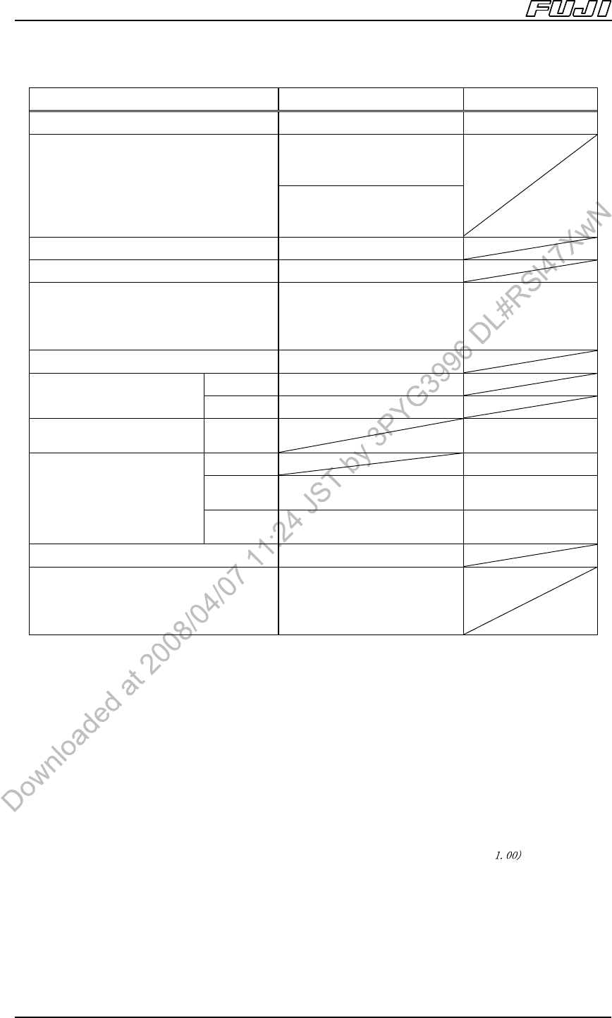
Items OF
Note 21
GL
Note 20
No. of nozzles/needles 1 nozzle or claw 1
<Standard camera>
Note 16
1608 (0603) ~ 74 x 74 mm
(32 x 180)
Part size
<Sidelight camera>
Note 16
1608 (0603) ~ 35 x 35 mm
(35 x 120)
Max. part height 25.4 mm (including leads)
Max. lead length 6.0 mm
Max. premounted part height
(upper surface)
Note 20
25.4 mm
0 mm (Z:4 mm)
0 mm (Z:6 mm)
3 mm (Z:8 mm)
7 mm (Z:12 mm)
Packaging Tape, Tray, Stick
Cpk≥1.00 ± 0.050
Note 19
Placing accurac
y
Note 13
(parts with leads)
Cpk≥1.33 ±0.066
Glue dispensing accuracy
Note 14
Cpk≥1.00 ±0.100
M3II 0.22 sec/dot
M6II
3000 (Frontlight/nozzle)
2500(Frontlight/claw)
same as above
Throughput
Note 15
CPH (chips/hr)
M6IISP
2800 (Frontlight/nozzle)
2000(Frontlight/claw)
same as above
Nozzle change Yes
Lead parts
Bump parts
Depends on the part
camera specification.
Refer to”4.5 Parts Camera
Unit”.
Notes:
13. The placement accuracy is based on tests conducted at Fuji.
14. The GL head dispensing accuracy is based on tests conducted at Fuji.
15. The throughput is based on tests conducted at Fuji.
16. The max. size of the short side of the part is 31 mm when using claws.
17. The glue temperature control function and application volume offset function are included with the GL head.
The optional units listed below are required when attaching the GL head.
a. Nozzle changer cover (for M3II or for M6II, M6IISP)
b. Parts camera cover
c. GCU (Glue Check Unit
18. OF head can be attached to M6II, M6IISP modules.
19. The placement accuracy with the nozzle after performing PAM is ± 0.030 mm (Cpk ≥ . The placement
accuracy, as well as note 15, is based on tests conducted at Fuji.
20. GL head premounted parts height differs depending on the Z axis stroke.