NXTII spec.pdf - 第25页
Machine S tructure Edition 2.0E - 25 - NXT II S pecifications 1-A-14-10 10 < L ≤ 30 1-A-14-30 30 < L ≤ 60 1-A-14-60 60 < L ≤ 105 Note: • The standard nozzle and claw set for the O F head co ntains 3 nozzle typ…
Machine Structure
Edition 2.0E - 24 - NXT II Specifications
4.7. Nozzles, Claws, and Needles
4.7.1. Nozzle and Claw Types
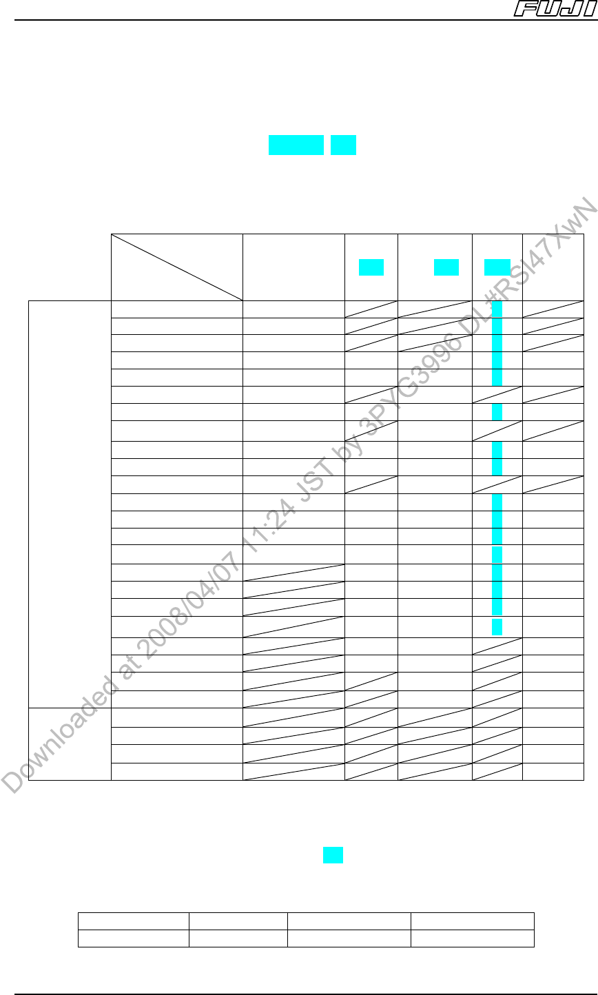
The H12HS [H12S], H08, H04/G04, H02 and H01 heads hold 12, 8, 4, 2 and 1
nozzles respectively, and the OF head holds 1 nozzle or claw. Supported
nozzles for each head are listed in the table below.
Placement
head
Head type
Note 1
H12HS
[H12S] /H08
Note 2
H04 H01,H02 G04 OF
φ0.3 O O
φ0.4 O O
φ0.7 O O
φ1.0 O O O
Note 3
O O
φ1.3 O O O O O
φ1.3M O O
φ1.8 O O O O O
φ1.8M O O
φ2.5 O O O O O
φ2.5G O O O O O
φ2.5M O O
φ3.7 O O O O O
φ3.7G O O O O O
φ5.0 O O O O O
φ5.0G O O O O O
φ7.0 O O O O
φ7.0G O O O O
φ10.0 O O O O
φ10.0G O O O O
φ15.0 O O O
φ15.0G O O O
φ20.0 O O
Nozzle
φ20.0G O O
1-A-14-4 O
1-A-14-10 O
1-A-14-30 O
Claw
Note 4,
5
1-A-14-60 O
Note:
1. The “G” suffix on the end of the nozzle size indicates nozzles fitted with a rubber pad. The “M” suffix on the
end of the nozzle size indicates nozzles designed for MELF parts.
2. The H12HS [H12S] and H08 heads use the same nozzles.
3. The premounted-part height when using the H01 or H02 head 1.0 mm nozzle is limited to 24.4 mm (Standard
specification: 25.4 mm).
4. The above listed claws for the OF head clasp the outside edges of all parts.
5. Supported part sizes for the above listed claws are as follows.
Tool No. Part width Part height Part length
1-A-14-4 1 ≤ W ≤ 31 3.5 ≤ H ≤ 25.4 4 < L ≤ 10
Machine Structure
Edition 2.0E - 25 - NXT II Specifications
1-A-14-10 10 < L ≤ 30
1-A-14-30 30 < L ≤ 60
1-A-14-60 60 < L ≤ 105
Note:
• The standard nozzle and claw set for the OF head contains 3 nozzle types (5.0G, 7.0G, 10.0G) and the 4
claw types listed above.
• A field with a slash indicates that a nozzle cannot be set.
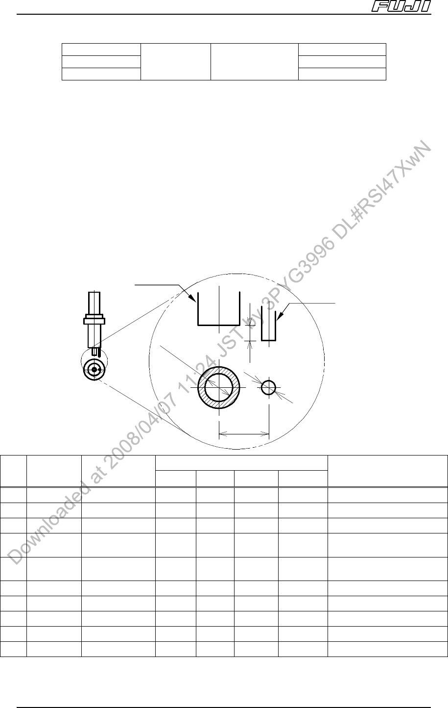
4.7.2. Needle Types
Only single needles are supported by the GL head.
A needle (inner diameter of φ0.58 mm) is attached as a standard accessory for
the GL head. Other needles can be purchased separately.
Note: The last digits of the drawing numbers (“**” shown in the table below) are changed each time
the design is changed.
Dimensions of each part
No.
Drawing Type
a b c d
Applicable Parts
1 AA5CT** φ1.0 Single φ1.0 φ0.5 1.8 mm 0.55 mm Large parts
2 AA3MC** φ0.9 Single φ0.9 φ0.5 1.7 mm 0.50 mm Medium to large parts
3 AA5CW** φ0.8 Single φ0.8 φ0.5 1.6 mm 0.45 mm Medium parts
4 AA3CR** φ0.7 Single φ0.72 φ0.7 1.5 mm 0.40 mm
General parts
excluding small chips
5 AA35N** φ0.6 Single φ0.58 φ0.7 1.5 mm 0.30 mm
General parts
excluding small chips
6 AA3MB** φ0.5 Single φ0.51 φ0.7 1.2 mm 0.25 mm 2125, 3216, SMIN, MIN
7 AA3MA** φ0.4 Single φ0.41 φ0.7 1.0 mm 0.20 mm 1608~3216, SMIN, MIN
8 AA3LZ** φ0.33 Single φ0.33 φ0.7 0.9 mm 0.15 mm 1608
9 AA3LY** φ0.3 Single φ0.30 φ0.7 0.9 mm 0.10 mm 1005, 1608
10 AA3LX** φ0.26 Single φ0.26 φ0.7 0.9 mm 0.10 mm 1005
Sto
pp
e
r
Needle
Ste
p
: d
Distance: c
Needle
Inner Dia.: a
Stopper
Outer dia.: b
Machine Structure
Edition 2.0E - 26 - NXT II Specifications
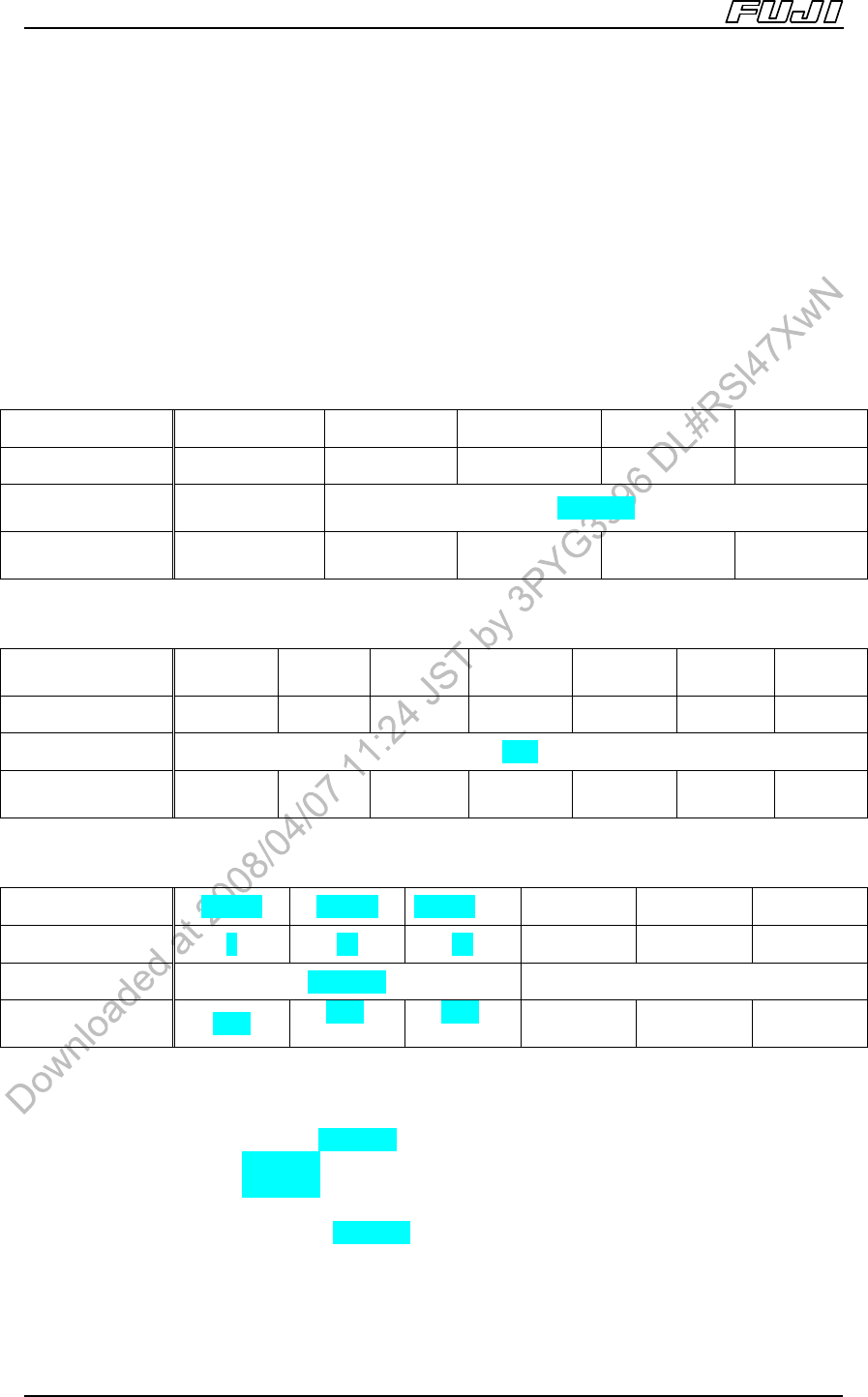
4.8. Nozzle Station
This unit holds the nozzles used for automatic nozzle change by the head. The
type differs depending on the head and module types.
All nozzle station types can be replaced in a simple one-touch operation, with
identification of new units performed automatically.
When using the GL head, a nozzle changer cover (same for M3II or M6II,
M6IISP) is attached to the nozzle changer.
Unit Type ND32C
Note 1
NE18A NE12A
Note 2
NEXTTA
Note 3
NERTTA
Note 5
Socket Qty. 32 18 12 24 18
Supported Nozzles
H12HS[H12S] /
H08 type
H04 type
Module Type
M3II, M6II,
M6IISP
M3II, M6II,
M6IISP
M6II, M6IISP M6II, M6IISP M6II, M6IISP
Unit Type NC03B NC08B
NC8LB
Note 2
NCPTA
Note 3,5
NCFTA
Note 4,5
NCKTA
Note 3
NCETA
Note 4
Socket Qty. 3 8 8 16 6 11 5
Supported Nozzles H01,H02 type
Module Type
M3II, M6II,
M6IISP
M6II,
M6IISP
M6II,
M6IISP
M6II,
M6IISP
M6II,
M6IISP
M6II,
M6IISP
M6II,
M6IISP
Unit Type NK08A NK15A NK12A
Note 2
NF08A NF07A
Note 6
NF05A
Note 7
Socket Qty. 8 16 12 8 7 5
Supported Nozzles G04 type OF type
Module Type M3II
M6II,
M6IISP
M6II,
M6IISP
M6II,
M6IISP
M6II,
M6IISP
M6II,
M6IISP
Note:
1. There is a ND32B type, but it is only for the H08 head.
2. Used when using a tray unit-L, tray unit-LT or two tray unit-Ms.
3. Used when using a tray unit-LT, and not using a coplanarity check unit.
4. Used when using a tray unit-LT, and using a coplanarity check unit.
5. Depending on the type of mechanical chuck, there may be units that cannot be stored.
6. Used when using a tray unit-L or tray unit-LT.
7. Used when using two tray unit-Ms.