NXTII spec.pdf - 第33页
S tandard F unctionality Edition 2.0E - 33 - NXT II S pecifications 6. S t andard Functionality 6.1. P ick-up Position Detection Pick-up accuracy is gu aranteed by performi ng part pick-up po sitio n detection immediat…
Machine Control System
Edition 2.0E - 32 - NXT II Specifications
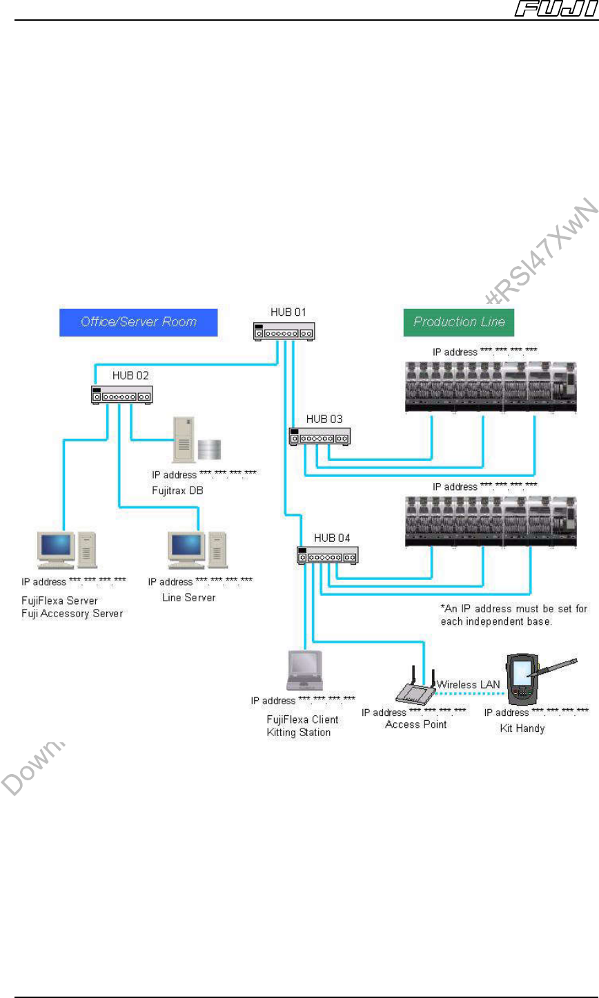
5.3. Cautions When Connecting to Network
Before connecting the cables for multiple PCs and network equipment, create a
network diagram that shows the equipment layout, host names and IP
addresses.
By creating this diagram the user can determine the required quantities of
switching hubs and LAN cables.
*Example Network Diagram:
Note
1. Exchanging of data between the NXTII and Fuji Flexa / Fujitrax can place a large load on a network.
Therefore, users should build an independent network to which the NXTII and Fuji Flexa / Fujitrax can be
connected so as to avoid overloading other networks.
2. Use a 100Base-TX compatible switching hub for the network. If connecting multiple network hubs, it may be
necessary to use cross cables and restrict port usage. For the connection procedure, refer to the manual for
your network hub.
3. Use a 100Base-TX compatible (Category 5 or higher) network cable. The network cable length should be
100 m or less. To make it easier to perform modifications or troubleshooting in future, affix a label to each
switching hub and LAN cable that identifies the name of the connection point, and include connection
relationships in the network diagram.
Standard Functionality
Edition 2.0E - 33 - NXT II Specifications
6. Standard Functionality
6.1. Pick-up Position Detection
Pick-up accuracy is guaranteed by performing part pick-up position detection
immediately after feeder replacement, pallet exchange, and head exchange.
6.2. Paired Production Mode (M3II Module)
Production is shared between two modules when the placement area exceeds
250 mm when producing a single panel on M3II modules.
The machine heads can place parts in the production area of the adjacent
module, therefore eliminating any dead space.
6.3. ZO Sensor
This sensor is used to measure the standard placing height.
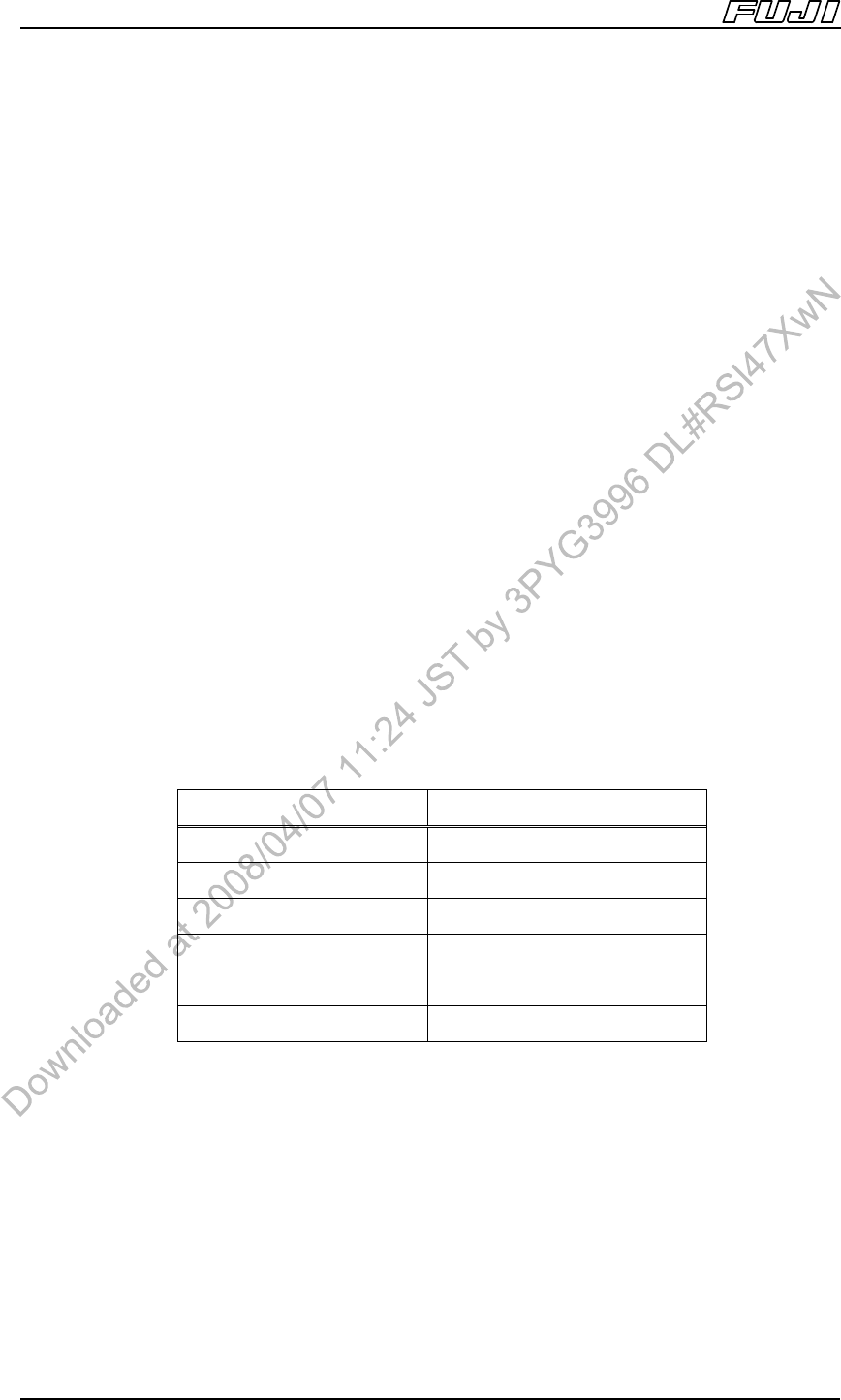
6.4. Auto Calibration
This function enables automatic placing accuracy compensation after such
things as heads, nozzle stations, feeders, and tray units have been replaced.
Dedicated jig nozzles are required to use this function.
Head No. of Required Nozzle Jigs
H12HS[H12S], H08 8
H04 4
G04 4
H02 2
H01 1
OF 1
Standard Functionality
Edition 2.0E - 34 - NXT II Specifications
6.5. HBC Function
This is a function of the M6IISP.
This function places the jig part in the jig stand, measures the placement error
amount, and adds the result to the placement correction measurement. When
combined with auto calibration, highly accurate placement is possible.
As well as the nozzle jigs for auto calibration, a separate nozzle jig for the HBC
function is required.
6.6. Placing Pressure Control
This function is used to control the force applied to parts and is available only for
the H01, and H02 heads. (Control range: 2.2 to 9.8 N)
6.7. Pressure Insertion Control
This function is used to support parts that require placement using pressure
insertion. Only H01, H02 and OF heads can use this function.
Supported range: 39.2 to 98N (for H01, H02 and OF heads)
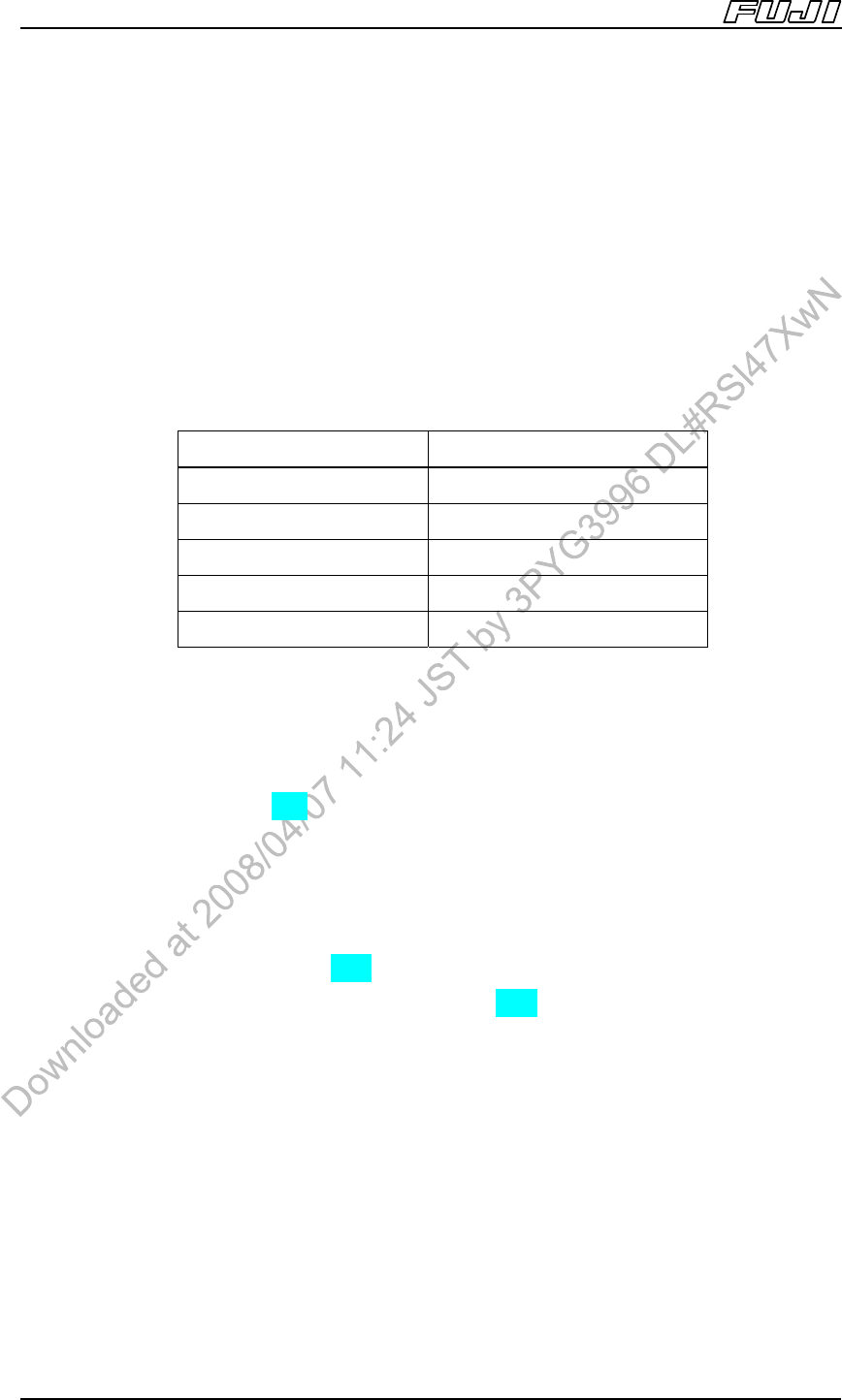
6.8. GCU (Glue Check Unit)
This unit is put on the device pallet and used together with the GL head.
The GL head dispenses glue dots on this unit and the machine measures needle
offset and the size of the dispensed glue.
Head No. of Required Nozzle Jigs
H12HS[H12S], H08 Φ1.3 1
H04 Φ5.0 1
G04 Φ1.3,Φ5.0 1 each
H01, H02 Φ1.3,Φ5.0 1 each
OF Φ5.0 1