NXTII spec.pdf - 第29页
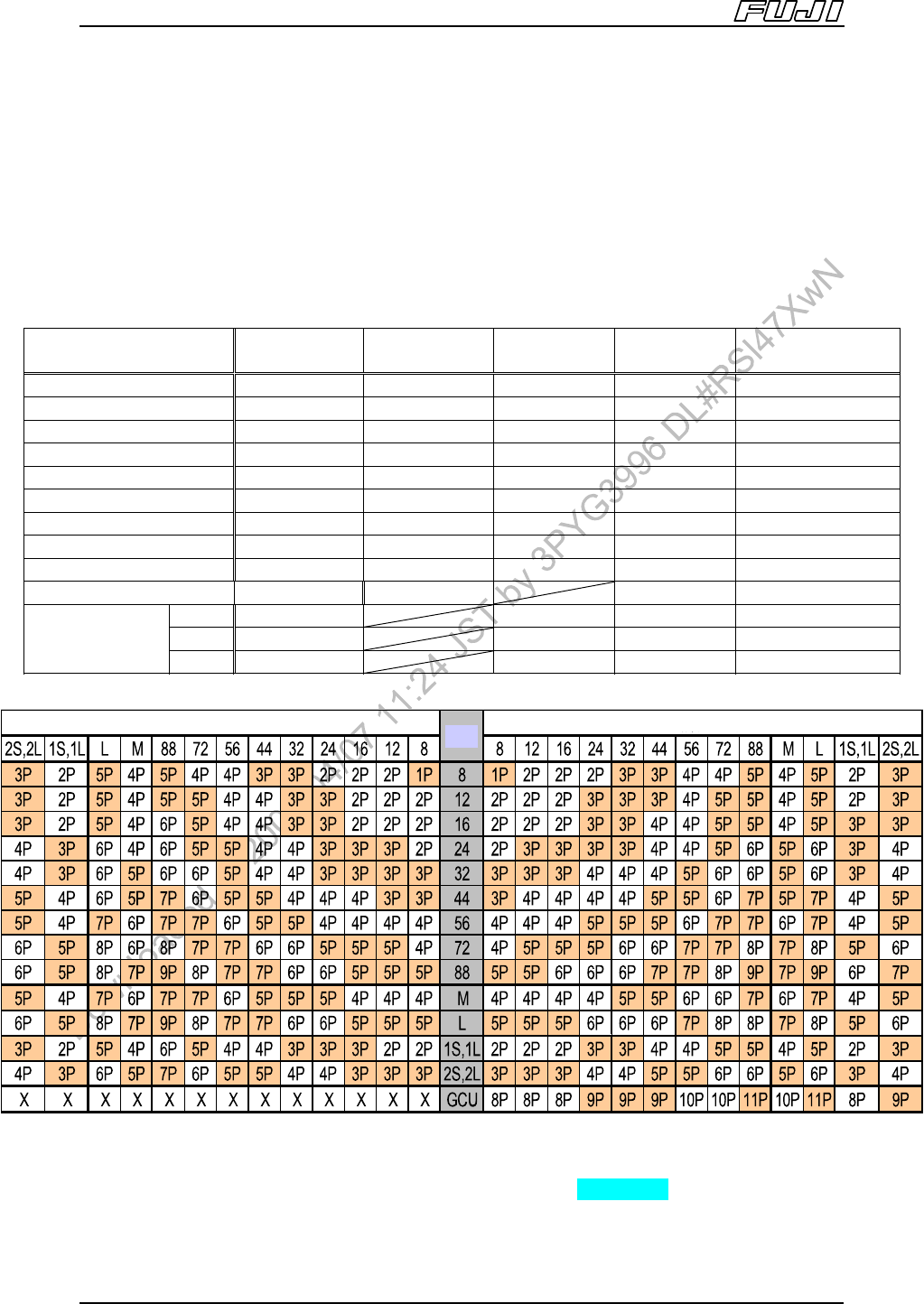
Machine S tructure Edition 2.0E - 29 - NXT II S pecifications 4.11. Loading Feeders at the Ends of a Pallet Slot No. Feeder 1 2 3 4 5 … 14 … 16 (41) 17 (42) 18 (43) 19 (44) 20 (45) W8 O O O O O O O O O O *1 W12 × O O O…
Machine Structure
Edition 2.0E - 28 - NXT II Specifications
4.10. Feeder Pallet with Attached Bucket
A pallet with attached bucket to enable W8 13-inch feeders to be loaded in one
pitch can now be selected as an option. The feeder reel holder is removed, and
in its place, the pallet with bucket is set on the machine. A dedicated feeder
pallet change unit (PCU) is required for pallets with buckets. A custom half
bucket is required when Tray unit-M is used alongside a pallet (M6II, M6IISP)
with an attached bucket.
Feeder Type
Occupied
Feeder slots
Occupied
Bucket slots
M3II Feeder
Capacity
M6II Feeder
Capacity
M6IISP Feeder
Capacity
W8 1 1 20 45 44
W12 2 2 9 22 22
W16 2 2 9 22 22
W24 3 2 6 15 15
W32 4 3 5 11 11
W44 5 4 4 9 9
W56 6 5 3 7 7
W72 7 6 2 6 6
W88 9 7 2 5 5
Single Stick Feeder 1S 2 9 22
1L 2 9 22 22
2S 4 4 11 22
2L 4 4 11 11
Note: M: Reject parts conveyor-M, L: Reject parts conveyor-L
1S/1L/2S/2L: Stick feeder type 1S/1L/2S/2L, GCU: Glue check unit
Note: This table represents a view of the feeders from the operator’s side. "X” in the table means that the feeder
type cannot be loaded. The number of slots and pitch required for W4P1 feeders is the same as for W8
feeders.
Left Side (Pitch)
Ref.
Right Side (Pitch)
Machine Structure
Edition 2.0E - 29 - NXT II Specifications
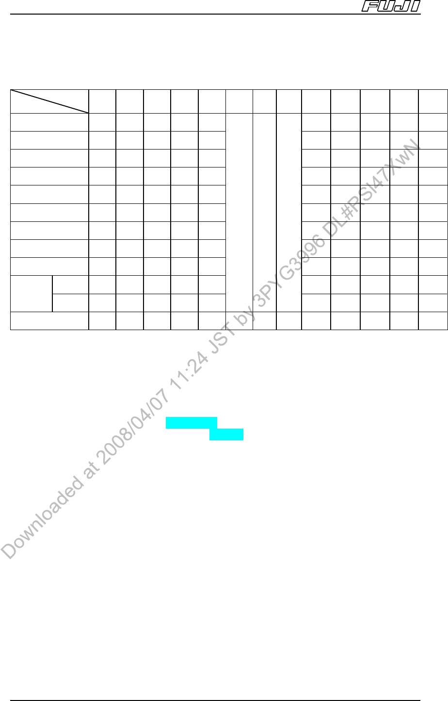
4.11. Loading Feeders at the Ends of a Pallet
Slot No.
Feeder
1 2 3 4 5 … 14 …
16
(41)
17
(42)
18
(43)
19
(44)
20
(45)
W8 O O O O O
O O O O
O
*1
W12 × O O O O
O O O O
×
W16 × O O O O
O O O O
×
W24 × O O O O
O O O O
×
W32 × × O O O
O O O O
×
W44 × × O O O O O O × ×
W56 × × × O O
O O O
× ×
W72 × × × O O O O × × ×
W88 × × × × O O × × × ×
Type1 × O O O O O
O O O
×
Single
Stick
Feeder
Type2 × × O O O
… … …
O O O × ×
GCU × × × × × … O … × × × × ×
Note:
Numbers in brackets in the “Slot #” row represent slot numbers for M6II, M6IISP modules.
Checks in the table indicate the slot numbers that each feeder can be set on.
Conditions are common regardless of the reel holder type (standard feeder reel holder specification, or bucket
specification).
GCU is loaded on slot 14.
The slots that are used when loading W4P1 feeders at the end of a pallet are the same as for W8 feeders.
The following slot positions cannot be used with a G04 head.
M3II module: No.1, 20
M6II module: No.1, 45
M6IISP module: No.1, 43~44
Machine Control System
Edition 2.0E - 30 - NXT II Specifications
5. Machine Control System
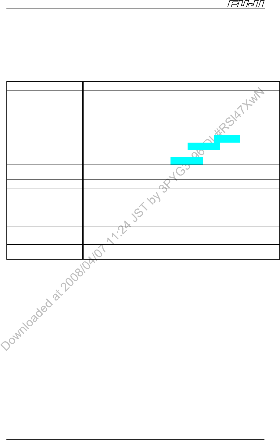
5.1. Machine Control Specifications
Item Specifications
Coordinate input method Absolute
Acceleration control (head) Acceleration/deceleration setting possible (3 stages)
Controllable axes
A total of 4 ~ 9 axes: X, Y, Z, Q, XS, R, TY, TZ, TZ1, TZ2
(No. of axes differ depending on the module, head and device
configurations.)
• The XS-axis is for the M3II module.
• The R-axis is for the H12HS [H12S, H12]/ H08/H04/G04 heads.
• The TY-axis is for the tray unit-L and tray unit-LT.
• The TZ-axis is for the tray unit-L.
• The TZ1, TZ2-axes are for the tray unit-LT.
Maximum number of input
sequences
2000 sequences/module
Maximum number of marks 3505 marks/job
Maximum number of
boards
1000 boards/job
Data input method
Note 1
(units)
Fuji Flexa:
X-, Y-, Z-axes: 0.01 mm
Q-axis: 0.01 degrees
Communication Network based (Ethernet)
Note 2
Optical correction For PCB positioning and part pick-up displacement
Operation panel
* Operator panel: Machine side operation
* Engineering panel: PC operation
Note 3
Note:
1. Data communication is performed using the Fuji Flexa host system.
A computer and host software are required in order to run Fuji Flexa. It is necessary to prepare the host
computer prior to taking receipt of your machine.
2. t is necessary to prepare an Ethernet cable prior to taking receipt of the machine. (100 base TX-cable (100 m
range.))
3. A computer for use with the engineering panel should be purchased by the user in advance. The Accessory
Software is a standard application of NXTII (refer to “8.1.1 NXT Accessory Software”)
* The NXTII can be treated as one machine with bases and modules connected together, however, the
maximum number of modules that can be connected is 32 when using only M3II) modules. M6II, M6IISP
modules are calculated as two M3II) modules. A line with more than 32 modules can be configured by setting
multiple machines within the line. (Settings performed at Fuji Flexa)