NXTII spec.pdf - 第19页
Machine S tructure Edition 2.0E - 19 - NXT II S pecifications 4. Machine S tructure Many parts of the NXT (bases, module s, heads, nozzle stations, device units, etc.) can be freely config ured. <Machine Configura t…
Machine Specifications
Edition 2.0E - 18 - NXT II Specifications
Items Specifications
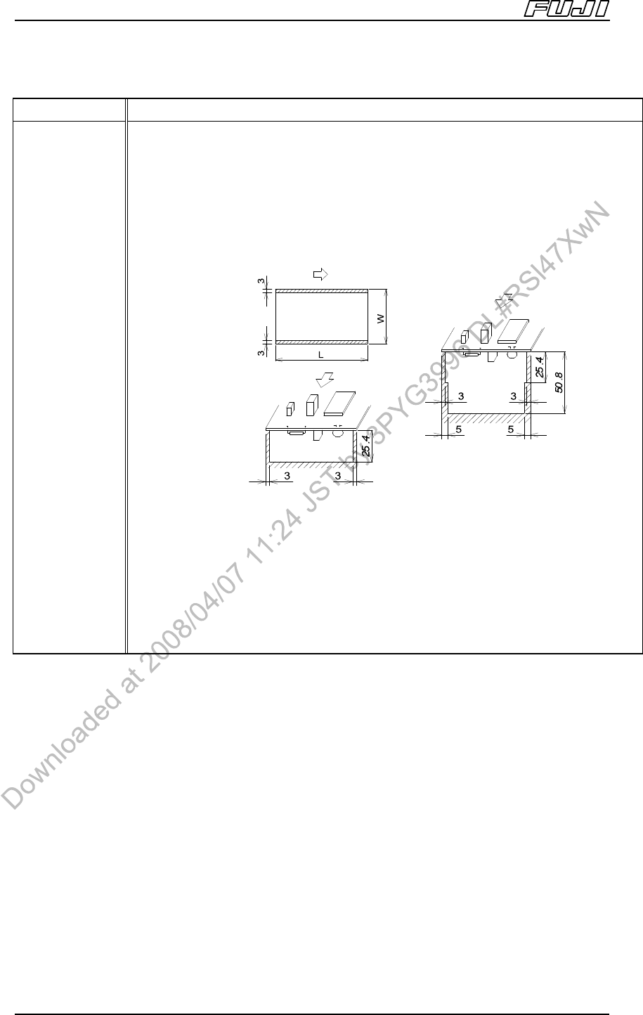
PCB conditions Warpage: Max. 2.0 mm
If downward PCB warpage occurs when the PCB is clamped, please use back-up
pins or a back-up plate to support the underside of the PCB.
Premounted part height: Differs depending on the head types (refer to “3.4 Head
Specifications”).
Premounted part height on lower surface: Max. 25.4 mm.
• No premounted parts possible in the shaded areas.
• 3 mm of dead space on both edges of the PCB is required for clamping.
• Contact Fuji if the PCB warpage is lower than the conveyance surface.
• It is necessary that 50% of the contact surface on the underside of the panel
indicated above be touching the conveyor surface. Furthermore, contact Fuji if
there are notches at both sides of the PCB and the PCB warpage is lower than
the conveyance surface.
<When using back-up pins>
< Without back-up pins>
<Bottom surface>
<Top surface>
* Without back-up pins: Max =
50.8mm.
Machine Structure
Edition 2.0E - 19 - NXT II Specifications
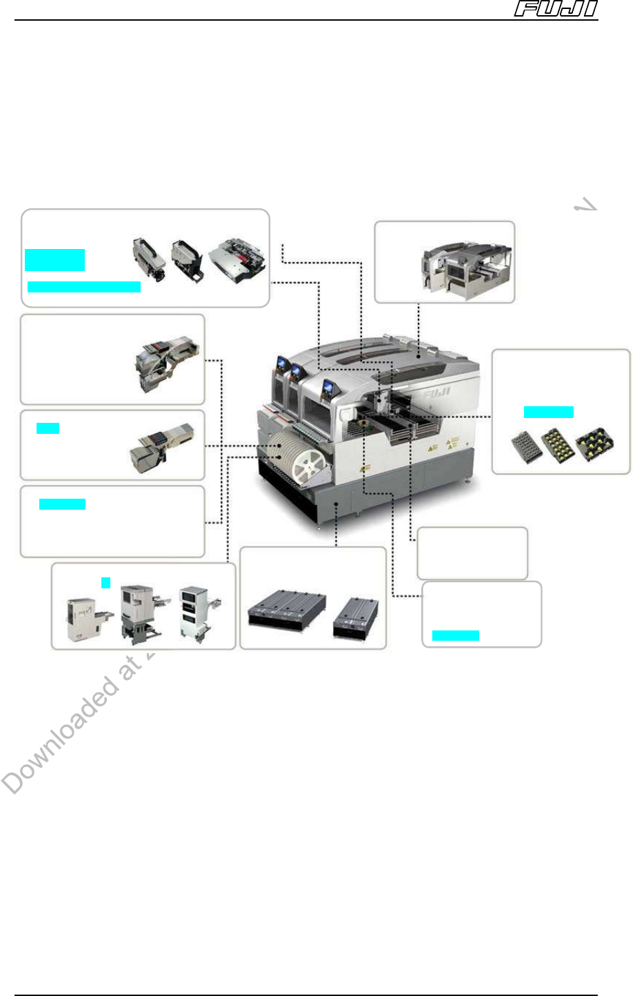
4. Machine Structure
Many parts of the NXT (bases, modules, heads, nozzle stations, device units,
etc.) can be freely configured.
<Machine Configuration Overview>
4.1. Machine Base
The base is the foundation upon which the modules are mounted. Bases are
available in two sizes (2MII-base and 4MII-base), depending on the line
configuration.
4.2. Modules
Each module comprises of an XY-robot, head, PCB conveyor, PCB clamper,
device unit, and vision system cameras.
Three sizes of modules are available: a 325 (W) mm M3II module, and a 650 (W)
mm M6II, M6IISP module. A module change unit is available, allowing the line to
be reconfigured easily by the user.
■
Module
- M3II
- M6II
- M6IISP
■
Mark camera
■
Main conveyo
r
-Double conveyor
-Single conveyor
■
Heads
-H12HS[H12S](12 nozzles)
-H08(8 nozzles)
-H04 (4 nozzles)
-H02 (2 nozzles)
-H01 (1 nozzle)
-G04 (High accuracy, 4 nozzles)
-OF (Insertion parts)
-GL (Glue)
■
Feeder Pallets
-For M3II 20 slots
-For M3II 20 slots
Bucket type
-For M6II 45 slots
-For M6II 45 slots
Bucket type
■
Feeders
-W4P1 -W8
-W12 -W16
-W24 -W32
-W44 -W56
-W72 -W88
■
Reel Holders
-W4/7 inches -W8/7, 13 inches
-W12/7, 15 inches -W16/15 inches
-W24/15 inches -W32/15 inches
-W44/15 inches -W56/15 inches
-W72/15 inches -W88/15 inches
■
Tray Units
-M -L -LT
■
Bases
-4MII base
-2MII base
■
Part Camera
-Standard camera
-Sidelight camera
-High resolution camera
-P03 camera
■
Nozzle Stations
-For H12HS[H12S/H12] /H08
(2 types)
-For H04 (4 types)
-For H01/H02 (7 types)
-For G04 (4 types)
-For OF (5 types)
Machine Structure
Edition 2.0E - 20 - NXT II Specifications
4.3. Heads
Depending on the parts being handled, eight different, easily exchangeable head
types are available: H12HS [H12] (12 nozzles), H08 (8 nozzles), H04 (4 nozzles),
H02 (2 nozzles), H01 (1 nozzle), G04 (4 nozzles, high accuracy placement), OF
(Supports insertion placement), and GL (Glue application).
4.4. Main Conveyor
The NXTII PCB conveyance system provides shock-free transport of the PCB,
with a motor driven, conveyor width adjustment function, and simple PCB flow
direction change capabilities.
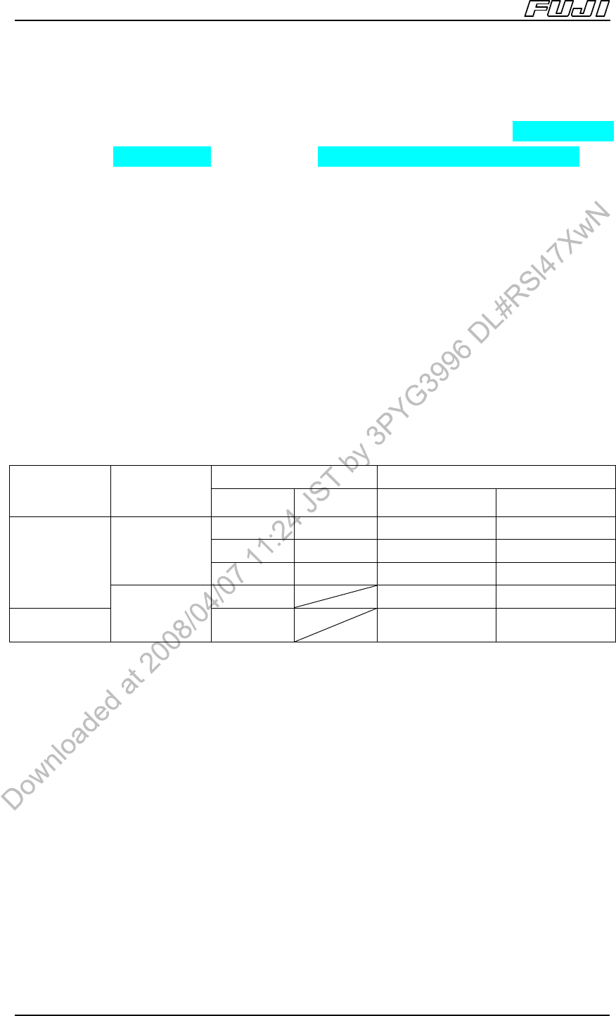
The double conveyor not only conveys and produces the same PCB, but can
also be used to convey and produce PCBs of different widths, and the conveyor
widths can be changed independently. Replace the back-up plates based on the
size of the PCB being produced.
PCB Size (W) (mm) Back-up Plate Size (W) (mm)
Conveyor
Specifications
PCB
Conveyance
Method
Lane 1 Lane 2 Lane 1 Lane 2
48~280 48~280 312
Note 1
312
Note 2
48~165 48~280 215
Note 3
312
Note 2
Double
conveyance
48~200 48~280 250
Note 3
312
Note 2
Double
conveyer
48~510 312
Note 1
312
Note 2
Single
conveyor
Single
conveyance
48~610 312
Note 4
312
Note 2
Notes:
1. Lane 1 back-up plate for double conveyor.
2. Lane 2 back-up plate for double conveyor.
3. When using this back-up plate, the rear conveyor is adjusted to a position further forward from the standard
position (PCB width: 280 mm). As a result, when producing PCBs on the rear conveyor, the Y-axis
movement distance is shorter when compared with the movement distance when the rear conveyor is at its
standard position, therefore resulting in a faster cycle time.
4. Backup plate for single conveyor.