NXTII spec.pdf - 第12页
Machine Specifications Edition 2.0E - 12 - NXT II S pecifications Less than 14 X Y Less than 18 3.4. Head Specification s Items H12HS[H12S] H08 H04 No. of nozzles 12 8 4 Part size (0402) Note 5 0603 ~ 5 × 5 mm (6 nozzle …
Machine Specifications
Edition 2.0E - 11 - NXT II Specifications
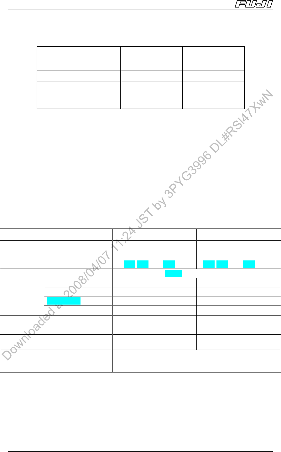
3.2. Base Specifications
Base Type
4MII base
(independent)
2MII base
(independent)
Vacuum pump O O
CPU board O O
Module Capacity
(Based on M3II module)
4 2
Configure your machine from a selection of the base sizes in the table above and
modules listed in the following module specification section.
When connecting bases, a connecting bracket is required regardless of the base
size or number of bases being connected.
An anchor bolts are required to secure the base when installing a 2MII base on
its own.
It is necessary to place adhesive sheets below the leveling sheets when
installing a 4MII base on its own or when connecting and installing two 2MII
bases.
3.3. Module Specifications
Items M3II Module M6II,M6IISP Module
Module width 325 mm
Note 1
650 mm
Note 1
Heads (selective type, one-touch
replacement available)
H12HS[H12S],H08,
H04,H02,H01,G04,GL
H12HS[H12S],H08,
H04,H02,H01,G04,OF,GL
Tape (W4P1)W8 ~ W88 mm
Stick O O
Tray unit-L X 1 unit
Tray unit-LT X 1 unit
Packaging
Tray unit-M X 1 or 2 units
L size O O
Reject parts
unit
Note 2
M size O O
Capacity (Using 8 mm tape with 7 inch
reel)
20 45 (44
Note 3
)
Standard back-up pin (magnet type)
PCB support
Auto back-up pin position function (option)
Notes:
1. A gap of 5 mm between each module has been added to the above figures for module width. The actual
dimensions for the above modules are 320 mm (M3II) and 645 mm (M6II, M6IISP) respectively.
2 Certain limitations exist based on the head type and parts height. (Refer to 7. Options.)
3. For the M6IISP, the capacity is 44.
Machine Specifications
Edition 2.0E - 12 - NXT II Specifications
Less than 14
X
Y
Less than 18
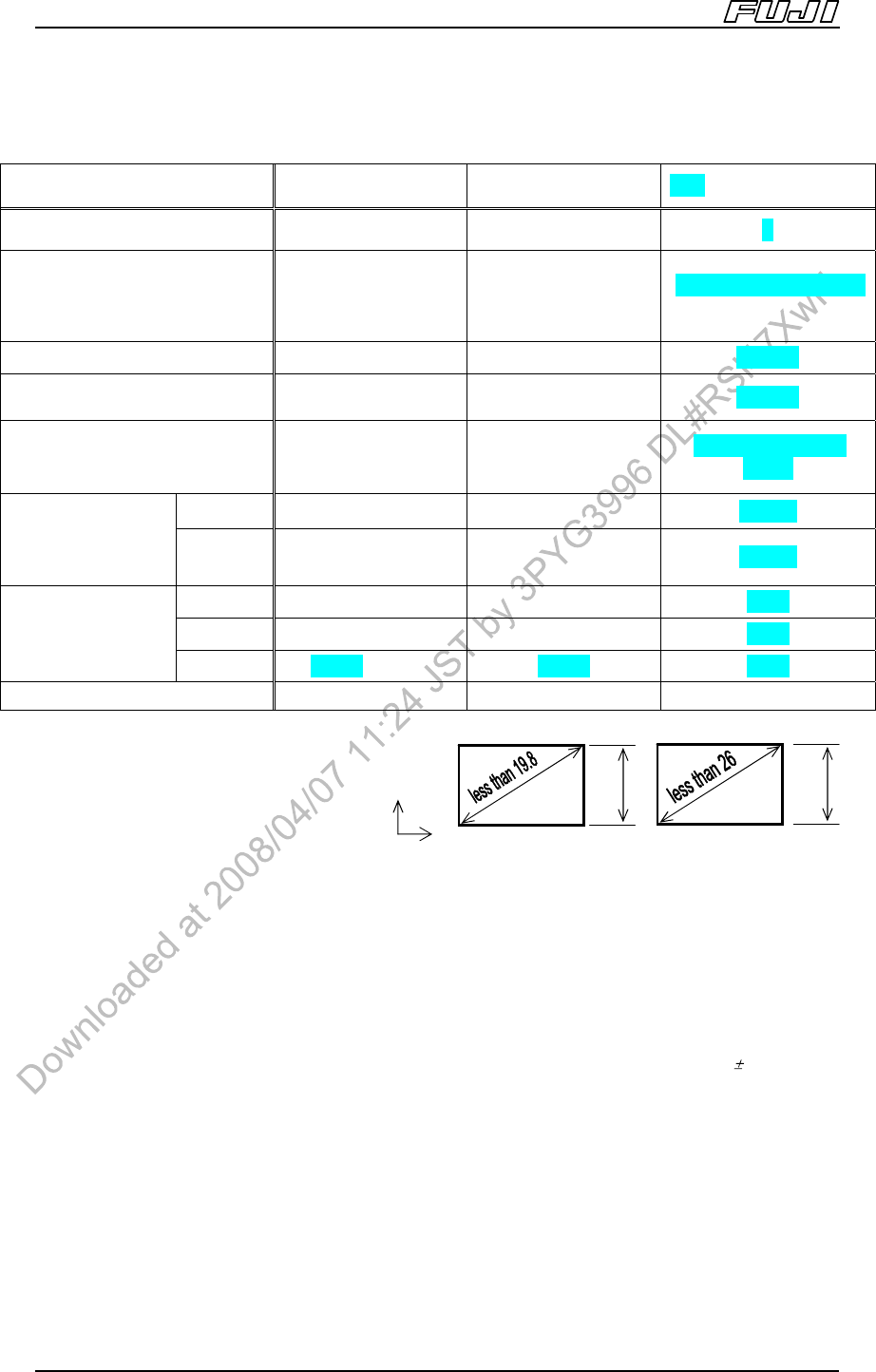
3.4. Head Specifications
Items H12HS[H12S] H08 H04
No. of nozzles 12 8 4
Part size
(0402)
Note 5
0603 ~
5 × 5 mm
(6 nozzle operation is 5 x 5
mm to 7.5 x 7.5 mm)
(0402)
Note 5
0603 ~
7.5 × 7.5 mm
(4 nozzle operation is 7.5 x
7.5 mm to 12 x 12 mm)
1608 (0603) ~ 38 x 38
Note 1
Max. part height 3 mm 6.5 mm 9.5 mm
Max. premounted part height
(upper surface)
3 mm 6.5 mm 9.5 mm
Packaging Tape Tape
Tape, Trays
Note 4
,
Sticks
Cpk≥1.00
±0.050 ±0.050 ±0.050
Placing accuracy
Note 2
(Rectangular chips and
small odd-form parts)
Cpk≥1.33
±0.066 ±0.066 ±0.066
M3II 22500 [18000] 11000 6500
M6II 22500 [18000] 11000 6500
Throughput
Note 3
(cph (chips/hr))
M6IISP 18500 [17000] 10000 6000
Nozzle change Yes Yes Yes
Notes:
1. 4 nozzle spec.: Max. 13 × 13 mm
2+2 nozzle spec.: Max. 14 x 14 mm
(or corner to corner dimensions of
19.8 mm or less and 14 mm or less
in the Y-direction) + 11 x 11 mm
2 nozzle spec.: Max. 18 x 18 mm
(or corner to corner dimensions of 26 mm or less and 18 mm or less in the Y-direction)
1 nozzle spec: Max. 38 × 38 mm
Parts for feeders and trays should be supplied in the XY-direction as shown in the diagram below.
2. The placing accuracy above is based on tests conducted at Fuji.
3. The throughput above is based on tests conducted at Fuji.
4. When using tray unit-L, parts less than 9 mm from the lower surface of the tray to the upper surface of the
parts are not supported. However, trays up to 29.5 mm in height (thickness) are supported.
5. The following conditions are required when placing 0402(01005) parts.
a. Manual offsetting using PAM is recommended when the required placement accuracy is 0.05 mm or
less.
b. Changes to Fuji Flexa nozzle spec data are required.
c. 0402 (01005) compatible feeders are required.
Machine Specifications
Edition 2.0E - 13 - NXT II Specifications
Items H12HS[H12S] H08 H04
Part size
~1.9 x
1.9
~2.8 x
2.8
~5 x 5
~2.4 x
2.4
~3.6x
3.6
~6.5x
6.5
~7.5
x 7.5
~9 x 9
~14 x
14
~26 x
26
~32 x
32
Min. pitch
(mm)
0.4 0.5 0.65 0.4 0.5 0.65 0.9
0.4 0.5 0.65 0.9
Min.
width/dia.
(mm)
0.17 0.2 0.3 0.17 0.2 0.3 0.4
0.17 0.2 0.3 0.4
Lead parts
Note 6
(Part size
includes leads)
Min. spacing
(mm)
0.23 0.3 0.35 0.23 0.3 0.35 0.5
0.23 0.3 0.35 0.5
Part size
~2.7 x
2.7
~3.8 x
3.8
~5 x 5
~3.4 x
3.4
~4.8
x 4.8
~7.5
x 7.5
~13 x
13
~19x 19
~32 x
32
Min. pitch
(mm)
0.5 0.65 0.5 0.5 0.65 1.0
0.5 0.65 1.0
Min.
width/dia.
(mm)
0.25 0.3 0.5 0.25 0.3 0.5
0.25 0.3 0.5
Bump parts
Note 6
Min. spacing
Between
bumps (mm)
0.25 0.35 0.5 0.25 0.35 0.5
0.25 0.35 0.5
6. The Bump parts specifications for H12S [H12], H08, and H04 heads, and the lead parts specifications for
H12S[H12]/H08/H04 heads will differ based on the part size. (Using the conditions for manual offsets based
on theoretical PAM.)
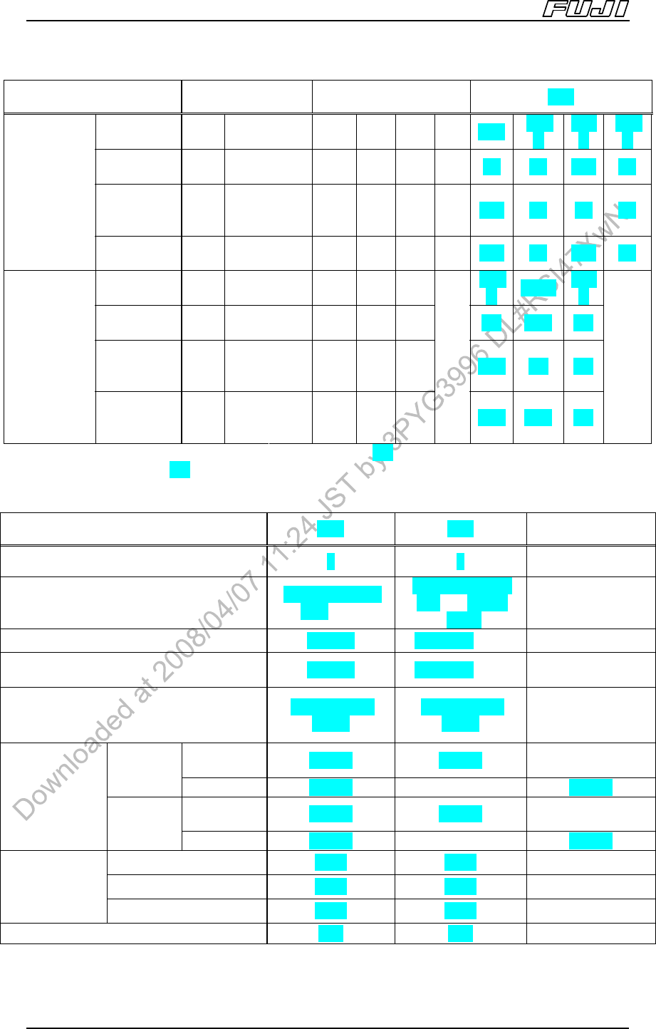
Items G04 H02 H01
No. of nozzles 4 2 1
Part size
0402 ~ 15 x 15
mm
Note 12
1608 ~ 74 × 74
mm
Note 9
(32 ×
180)
1608 ~ 74 × 74
mm (32 × 180)
Max. part height 6.5 mm 25.4 mm
Note 10
25.4 mm
Max. premounted part height (upper
surface)
6.5 mm 25.4 mm
Note 10
25.4 mm
Packaging
Tape, Trays,
Sticks
Tape, Trays,
Sticks
Tape, Trays,
Sticks
M3II, M6II
±0.030 ±0.030
± 0.030
± 0.050
Note 11
Cpk
≥
1.00
M6IISP
±0.018 ±0.018 ±0.018
M3II, M6II
±0.040 ±0.040
± 0.040
± 0.066
Note 11
Placing
accuracy
Note 7
(parts with leads)
Cpk
≥
1.33
M6IISP
±0.024 ±0.024 ±0.024
M3II 6800 5600 4200
M6II 6800 5600 4200
Throughput
Note 8
(cph
(chips/hr))
M6IISP 6200 4700 3500
Nozzle change Yes Yes Yes