00192377-02.pdf - 第115页
SIPLACE S-23 HM 2 Retrofitting Instruct. S-23 HM to SW V 502.xx incl. RV6-DLM 1 Head (Option) 07/01 Issue 2.10 SITEST: Adjust Configuration, Entry Zero Point Compens. Values RV6 Head 115 Å If further optio ns were instal…
2 Retrofitting Instruct. S-23 HM to SW V 502.xx incl. RV6-DLM1 Head (Option) SIPLACE S-23 HM
2.10 SITEST: Adjust Configuration, Entry Zero Point Compens. Values RV6 Head 07/01 Issue
114
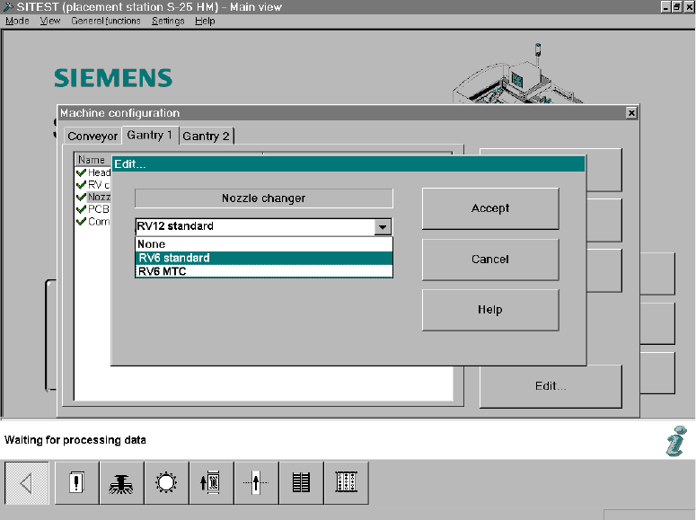
Fig. 2.10.3 SITEST Screen Machine Configuration, Edit
Å Click on "RV6 Standard" (long nozzle changer for the RV6 head) -> Select "Accept" (button).
Note:
If an MTC was retrofitted during the upgrading process, select the nozzle changer "RV6 MTC"
-> "Accept" (button) -> again "Accept".
After the overall reference run, the nozzle changer MTC is configured and measured in accor-
dance with the retrofitting instructions for MTC, Item no. see: Section 2.7.
Å Calibrate the nozzle changer after the dynamics adjustment and the calibration of the heads,
i.e., after taking the steps below (see: Section 2.13).
2.10.4 Configuration: Conveyor, Component Reject Box, etc.
Å Select "Conveyor" (registration card):
The configuration that was current prior to the software upgrade will appear.
If the configuration has to be changed, click on the menu option to be adjusted -> "Edit" ->
Change the configuration (e.g., dual/single conveyor, etc.)
-> "Accept".
Å If an MTC was installed during the upgrading process, select the type of component reject box
that was installed ("Component reject box MTC" or "Component reject table") -> Accept
For details -> Retrofitting instructions MTC (Item no. see: Section 2.7), from issue status 02.
SIPLACE S-23 HM 2 Retrofitting Instruct. S-23 HM to SW V 502.xx incl. RV6-DLM1 Head (Option)
07/01 Issue 2.10 SITEST: Adjust Configuration, Entry Zero Point Compens. Values RV6 Head
115
Å If further options were installed during the upgrading process, configure them in accordance
with the relevant retrofitting instructions (Item no. see: Section 2.7).
2.10.5 Configuration of Interface
The "Conveyor interface" SMEMA or SIEMENS interface can be selected in the software
V 502.01, however the setting must always be SIEMENS because the interface signals on these
machines, S-23 HM / S-25 HM, are always converted entirely on the SMEMA assembly. 2
-> A change will evoke an error message! 2
2.10.6 Concluding Acceptance of the Configuration
Å After completely adjusting the machine configuration:
Exit the menu "Machine Configuration" by pressing "Accept" (button).
The main view will be displayed and the messsage will appear:
The machine configuration has changed.
Shut down -> Restart machine -> Click on "OK" (button)
Å Boot up the machine and change back to the SITEST program.
2.10.7 Entry for the Zero Point Compensation Values of the New Placement Head
Å AFTER the restart, transfer the zero point compensation values on the label of the place-
ment head just installed (visible in assembled condition).
Å For the entry, select the menu "Head exchange" in the SITEST main view or select:
-> ICON "Axis functions of the revolver head" -> Activate the relevant axis (z-, star, dp) by
clicking on the radio button -> Click on "Positions" (button).
Å Select "Zero point compensation" -> Edit -> Transfer the value from the label -> Click on
"Accept" (button)
Å Carry out the transfer of the remaining zero point compensations from the label in the same
manner.
Å Now carry out the overall reference run (button).

2 Retrofitting Instruct. S-23 HM to SW V 502.xx incl. RV6-DLM1 Head (Option) SIPLACE S-23 HM
2.11 Setting the Dynamics 07/01 Issue
116
2.11 Setting the Dynamics
CAUTION
After exchanging a placement head the setting of the dynamics must always be checked.
When changing from the 12- to the 6-segment head (optional) in particular, the Z-axis is much too
fast and the P-component much too low.
It is IMPERATIVE that the dynamics be set.
In addition, when the modular head board (optional) is installed, the track signals must also be
calibrated. 2
Å For the new 6-segment revolver head, modular, calibrate the Z-axis and the dp-axis.
To do so, proceed according to the setting instructions in SITEST -> Help -> Setting of
dynamics or according to the setting instructions (Item no. see: Section 2.7).
2.12 Calibrating the Placement Heads and Cameras
Requirements:
– The dynamics must be set.
– To use the final operating conditions as a basis, we recommend that the protective covers of
both placement heads be mounted first.
NOTE:
If errors occur during the calibration, you may be using the incorrect axis data.
Consequence: During calibration, the part to be calibrated is only turned 45° or the machine’s zero
point is incorrect (by 5 mm or a multiple thereof).
If an error occurs, change the configuration back to the 12-segment head and then back to the
6-nozzle head. 2
ÅCalibrate the "Placement heads and cameras" as described in the Software Guide
SITEST V 502.xx.
This calibration is a prerequisite for measuring the nozzle changer.
2