00192377-02.pdf - 第92页
2 Retrofitting Instruct. S-23 HM t o SW V 502. xx incl. RV 6-DLM1 Head (O ption) SIPLACE S -23 HM 2.8 Sequence: M odifying Hardware 07/01 Issue 92 2 Fig. 2.8.13 Undoing Screw s Fastening Cable Harnes s; Undoing Connect i…
SIPLACE S-23 HM 2 Retrofitting Instruct. S-23 HM to SW V 502.xx incl. RV6-DLM1 Head (Option)
07/01 Issue 2.8 Sequence: Modifying Hardware
91
2.8.7.1 De-installation of the 12-Segment Revolver head (DLM1)
2
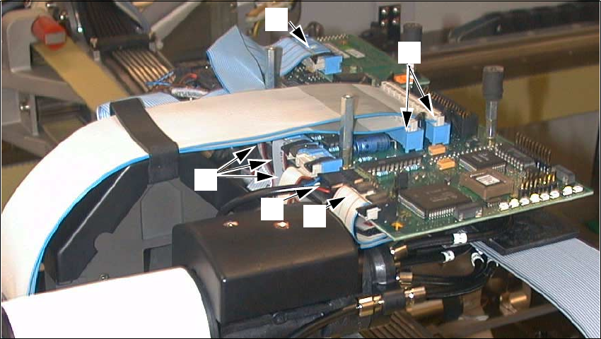
Fig. 2.8.12 De-installation of the RV12 Placement Head, DLM1: Removing the Connections
Key:
1. Ribbon cable "Vacuum board"
2. Round cable "Revolver head" (motor, tachometer)
3. 3 ribbon cables "Stepped motors/Photoelectric barrier"
4. 1 ribbon cable "Illumination PCB camera (illlumination board)
5. 2 ribbon cables, wide
Å Remove the 4 protective covers from the placement head and unscrew socket hex head cap
screws M3 and 2.5.
Å Undo the connectors of the front part of the placement head at the "Conversion board, small
axis" and on the illumination board (see: Fig. 2.8.12 -> 1 to 5).
2
1
3
5
4
2 Retrofitting Instruct. S-23 HM to SW V 502.xx incl. RV6-DLM1 Head (Option) SIPLACE S-23 HM
2.8 Sequence: Modifying Hardware 07/01 Issue
92
2
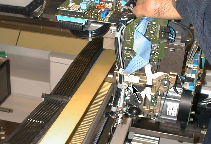
Fig. 2.8.13 Undoing Screws Fastening Cable Harness; Undoing Connections on Conversion Board
Å Undo the screw fastening the cable clamp that holds the cable harness running downward
(see: arrow, Fig. 2.8.13, 1 socket hex head cap screw M3).
SIPLACE S-23 HM 2 Retrofitting Instruct. S-23 HM to SW V 502.xx incl. RV6-DLM1 Head (Option)
07/01 Issue 2.8 Sequence: Modifying Hardware
93
2
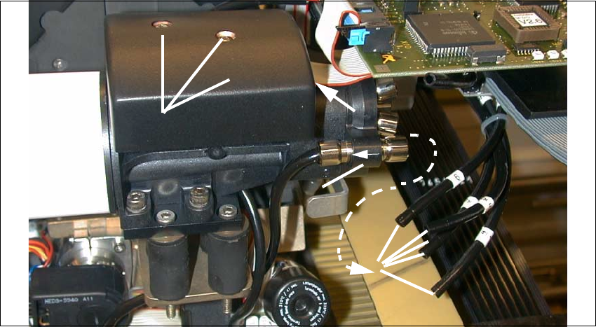
Fig. 2.8.14 De-installation 12-Segment Rev. Head: Detaching Pneumatic Hoses from Vacuum Generator
Key:
1. Compressed air feeder to the vacuum generator (5 hoses)
2. Collar on compressed air connection to the blast unit (support while pulling hoses off).
3. Cover over vacuum distributor board
(Fasteners: 2 socket hex head cap screws M2.5)
4. Ribbon cable: Connection on vacuum distributor board
Å Pull off the 5 compressed air hoses on the vacuum generator (see: Fig. 2.8.14).
Support in the case of the quick-release coupling (-> 2).
Å Remove the cover from the vacuum distributor board (loosen 2 socket hex head cap screws
M2.5, size 3).
Å Pull the 2 silicone hoses off the vacuum distributor board.
Å Pull the 2 silicone hoses off the silencer.
Å Support the placement head:
Undo the screws fastening the placement head: 3 socket hex head cap screws M4.
The head is still held in position by pins.
Å Pull the placement head (pins in the part to be pulled off) off the back part and set it down such
that it is not damaged, preferably in the proper package.
2
1
3
4
2