00192377-02.pdf - 第95页
SIPLACE S-23 HM 2 Retrofitting Instruct. S-23 HM to SW V 502.xx incl. RV6-DLM 1 Head (Option) 07/01 Issue 2.8 Sequence: Modifying H ardware 95 NOTE: If metal brack ets are still installed in the pre sent 12-segm ent rev …
2 Retrofitting Instruct. S-23 HM to SW V 502.xx incl. RV6-DLM1 Head (Option) SIPLACE S-23 HM
2.8 Sequence: Modifying Hardware 07/01 Issue
94
2.8.7.2 Preparing the New 6-Segment Revolver Head (RV6-DLM1)
2
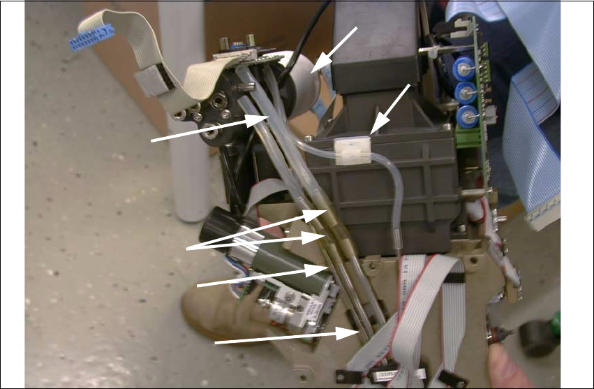
Fig. 2.8.15 New Placement Head: Mounting 3 Extensions (Steel Tubes), BOTTOM
Key:
1. Vacuum generator with silencer (fasteners: 4 socket hex head cap screws M4)
2. Silicone hoses am the vacuum distributor
3. NEW extension to be installed:
2 tubes 35 mm long (enclosed package in the retrofit kit, see: Section 2.5)
4. NEW extension to be installed:
1 tube 30 mm long (enclosed package in the retrofit kit, see: Section 2.5)
5. Vacuum feeders to the star (metal tube, fixed).
6. Vacuum hose, fastened with round-cable clamp (vacuum check for holding circuit).
Å Take the 6-Segment revolver head (DLM1) out of the retrofit kit.
Å Pull the silicone hoses of the vacuum generator and the vacuum board off the new placement
head.
Å Remove the vacuum generator incl. silencer from the new placement head so that you can
mount the metal-rubber vibration dampers from the enclosure pack later:
Undo 4 socket hex head cap screws M4 (see: and Fig. 2.8.16 and Fig. 2.8.18).
2
3
5
4
6
1

SIPLACE S-23 HM 2 Retrofitting Instruct. S-23 HM to SW V 502.xx incl. RV6-DLM1 Head (Option)
07/01 Issue 2.8 Sequence: Modifying Hardware
95
NOTE:
If metal brackets are still installed in the present 12-segment revolver head (RV12-DLM1) instead
of rubber-metal vibration dampers, these brackets must be exchanged for these dampers as
described below for the 6-segment revolver head DLM1). 2
Å Extend the length of the vacuum hoses as outlined in the conversion instructions, Item no.
00191684-03:
Push the extensions (tube from the retrofit kit) onto the FIXED metal tubes = BELOW (see: Fig.
2.8.15).
Place the existing hose pieces onto the tube in the correct order (length!).
Å Now install the Velcro-type fastener on the bottom of the head board because this location is
better accessible before the head is installed (see: Fig. 2.8.17).
Å The vacuum generator with silencer remains dismantled for the time being because it is more
practical not to mount this until after you have installed the placement head.
Å Mount the placement head as described below.
2 Retrofitting Instruct. S-23 HM to SW V 502.xx incl. RV6-DLM1 Head (Option) SIPLACE S-23 HM
2.8 Sequence: Modifying Hardware 07/01 Issue
96
2.8.7.3 Installing the New 6-Segment Revolver Head (RV6-DLM1)
NOTE:
If the optional PCB camera Multicolor will be installed during the upgrading process, the modular
head board must now be installed first (retrofitting instructions (Item no. see: Section 2.7). This
modification must always be performed on both gantries because the Multicolor camera is always
installed on both gantries. 2
2
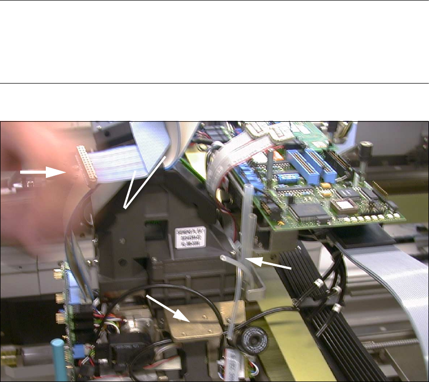
Fig. 2.8.16 Pushing the 6-Segment Revolver Head onto Pins of the Head Support and Screwing It Tight
Key:
1. 4 silicone hoses, connection to silencer and vacuum generator
2. Vacuum generators with silencers are still dismantled at this point.
3. Push placement head on.
4. Re-use 2 wide ribbon cables from the de-installed head.
(Do this with ribbon cable "Illumination board" also -> see: Fig. 2.8.12)
Å The silencer has not been installed yet (see: Fig. 2.8.16 -> 2).
Å Push the placement head which has been thus prepared (3 extended vacuum tubes) onto the
back portion on the gantry:
Screw the head tight (3 socket hex head cap screws M4).
1
3
4
2