00192377-02.pdf - 第99页
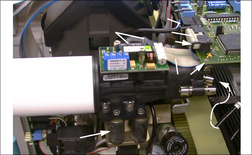
SIPLACE S-23 HM 2 Retrofitting Instruct. S-23 HM to SW V 502.xx incl. RV6-DLM 1 Head (Option) 07/01 Issue 2.8 Sequence: Modifying H ardware 99 2 Fig. 2.8.18 Installing Vibrat. Dampers (Retrofit Kit); Making Connection to…

2 Retrofitting Instruct. S-23 HM to SW V 502.xx incl. RV6-DLM1 Head (Option) SIPLACE S-23 HM
2.8 Sequence: Modifying Hardware 07/01 Issue
98
Å Make the connections of the 3 ribbon cables "Stepped motor" and the round cable "Revolver
head" (motor, tachometer) on the board.
Press the 3 ribbon cables with the 3 Velcro-type connections against the board holder.
Å Install the 4 new rubber-metal vibration dampers from the retrofit kit on the new head
(see: Fig. 2.8.18 -> 1), as described in detail in the conversion instructions
DLM1 Col-
lect&Place head, Item-No. 00191684-03.
CAUTION
If, instead of the rubber-metal vibration dampers, a metal bracket is still installed on the remaining
RV12-DLM1 head, the bracket must be replaced by the dampers (from a 2 enclosed package).
De-install the vacuum generator incl. silencer and proceed as described in the conversion instruc-
tions (see above). 2
Å Place the vacuum generator incl. silencer on the adapter plate and screw it tight (4 washers
A 4.3 und 4 socket hex head cap screws M4; size 3, in the enclosed package).
The enclosed package contains all fastening parts.
Å If applicable, remove the cover from the vacuum generator (2 socket hex head cap screws
M2.5; size 2).
Å Connect the ribbon cable "Vacuum board" to the conversion board / modular head board.
Secure it to the bottom of the board with the Velcro-type fastener (see: Fig. 2.8.18 -> 2).
For details -> see: conversion instructions for the DLM1 head.
Å Fold down all black terminal strips (see: Fig. 2.8.18 -> 5).
SIPLACE S-23 HM 2 Retrofitting Instruct. S-23 HM to SW V 502.xx incl. RV6-DLM1 Head (Option)
07/01 Issue 2.8 Sequence: Modifying Hardware
99
2
Fig. 2.8.18 Installing Vibrat. Dampers (Retrofit Kit); Making Connection to Vacuum Board
Key:
1. 4 Rubber-metal vibration dampers (enclosed package from retrofit kit)
2. Velcro-type fastener (enclosed package from retrofit kit)
3. Ribbon cable "Vacuum board" (present on the new head)
4. Strain relief bow on the socket connector (removed for "Conversion board, small axis")
5. 2 terminal strips
6. Round cable "Revolver head" (tachometer, motor) presnt on new head)
7. Pneumatic hoses, compressed air feed to the vacuum generator
8. Connection of the silicone hoses
Å Connect the 5 compressed air feeders - in correct order (number is on the hose) - to the vac-
uum generator and the blast unit (see: Fig. 2.8.18 -> 7).
Å Connect the sets of 2 thin silicone hoses to the vacumm board in the correct order (see: Fig.
2.8.18 -> 8).
Å Connect the 2 thick silicone hoses to the vacuum generator in the correct order.
1
5
7
2
8
3
4
6
2 Retrofitting Instruct. S-23 HM to SW V 502.xx incl. RV6-DLM1 Head (Option) SIPLACE S-23 HM
2.8 Sequence: Modifying Hardware 07/01 Issue
100
Å Mount the cover on the vacuum generator (2 socket hex head cap screws M2.5;
size 2).
Å Mount the new head cover of the 6-segment revolver head from the retrofit kit.
Take note of: The difference between the cover of the 6-segment head and 12-segment head
is scarcely visible.
Take note of: The item number of the 6-segment head cover is 00329003-01.
2.8.8 Option: Installing Nozzle Changer for 6-Segment Head, RV6 Standard
NOTE:
If you install the optional MTC during the upgrading, you have to install the nozzle changer MTC.
In this case, proceed on the basis of the "Retrofitting instructions MTC on S-25 HM" (Item no. see:
Section 2.7). 2
DANGER
As for all other installation steps related to upgrading, the machine must be turned OFF and iso-
lated from the mains, especially for all work in the vicinity of the cutter.
In addition, the compressed air feeder at the main valve of the compressed air unit in the machine
frame must be turned OFF and the compressed air lines bled by actuating the needle valve on the
compressed air unit.
Never reach into the cutter from above or below. Even when the machine is OFF, you can still in-
jury yourself on the blades of the cutter.
Secure the machine conscientiously as described in the chapter "Locking the Machine..." in the
User Manual to prevent it from being turned back ON without authorization. 2
2
2.8.8.1 De-installing: Nozzle Changer for 12-Segment Head (RV12 Standard)
Do the following whenever a 6-segment revolver head has been installed during the course of the
upgrading. This head requires the nozzle changer RV6 Standard from the retrofit kit. 2
NOTE:
S-23 HM machines that are upgraded during the Siemens Dematic commissioning already have
NO nozzle changer upon receipt in Bruchsal. In this case, proceed with the section "Installing ...". 2