00192377-02.pdf - 第117页
SIPLACE S-23 HM 2 Retrofitting Instruct. S-23 HM to SW V 502.xx incl. RV6-DLM 1 Head (Option) 07/01 Issue 2.13 Loading and Calibrating S ITEST Nozzle Change r RV6 Standard with Noz zles 117 2.13 Loading an d Calibrating …

2 Retrofitting Instruct. S-23 HM to SW V 502.xx incl. RV6-DLM1 Head (Option) SIPLACE S-23 HM
2.11 Setting the Dynamics 07/01 Issue
116
2.11 Setting the Dynamics
CAUTION
After exchanging a placement head the setting of the dynamics must always be checked.
When changing from the 12- to the 6-segment head (optional) in particular, the Z-axis is much too
fast and the P-component much too low.
It is IMPERATIVE that the dynamics be set.
In addition, when the modular head board (optional) is installed, the track signals must also be
calibrated. 2
Å For the new 6-segment revolver head, modular, calibrate the Z-axis and the dp-axis.
To do so, proceed according to the setting instructions in SITEST -> Help -> Setting of
dynamics or according to the setting instructions (Item no. see: Section 2.7).
2.12 Calibrating the Placement Heads and Cameras
Requirements:
– The dynamics must be set.
– To use the final operating conditions as a basis, we recommend that the protective covers of
both placement heads be mounted first.
NOTE:
If errors occur during the calibration, you may be using the incorrect axis data.
Consequence: During calibration, the part to be calibrated is only turned 45° or the machine’s zero
point is incorrect (by 5 mm or a multiple thereof).
If an error occurs, change the configuration back to the 12-segment head and then back to the
6-nozzle head. 2
ÅCalibrate the "Placement heads and cameras" as described in the Software Guide
SITEST V 502.xx.
This calibration is a prerequisite for measuring the nozzle changer.
2
SIPLACE S-23 HM 2 Retrofitting Instruct. S-23 HM to SW V 502.xx incl. RV6-DLM1 Head (Option)
07/01 Issue 2.13 Loading and Calibrating SITEST Nozzle Changer RV6 Standard with Nozzles
117
2.13 Loading and Calibrating SITEST Nozzle Changer
RV6 Standard with Nozzles
NOTE:
In SITEST V 502.01 the nozzles on the head and in the nozzle changer are now monitored, as is
the case with the station software.
For the nozzle changer MTC, proceed as described in "Retrofitting instructions MTC on S-25 HM"
(see: Section 2.7). 2
Requirements:
– The new placement head(s) DLM1 (6-segment) and the nozzle changer(s) RV6 Standard
must be configured (see: Section 2.10).
– All placement heads and cameras must have been calibrated already (see: Section 2.12).
2.13.1 Loading with Nozzles
Å
Starting from the SITEST main view, select
the ICON "Revolver heads" -> and
then "Revolver head 1" or "Revolver head 2" .
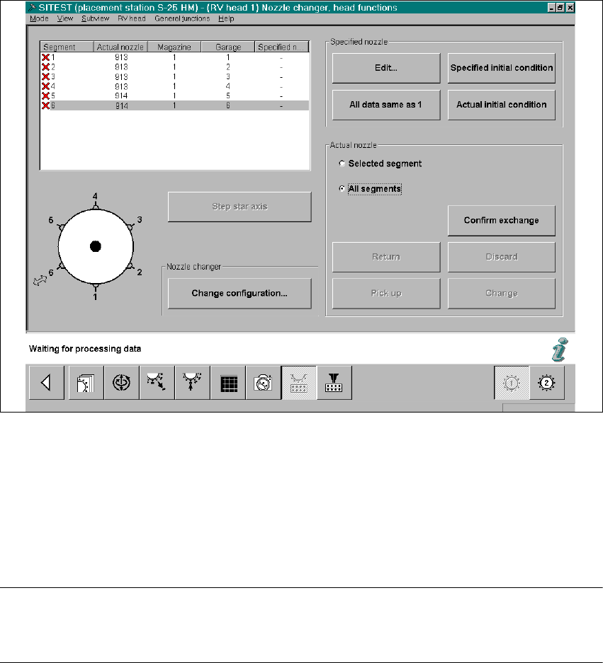
Å In the menu "Functions", click on the ICON "Nozzle changer head functions" .
The following will appear on the screen:
2 Retrofitting Instruct. S-23 HM to SW V 502.xx incl. RV6-DLM1 Head (Option) SIPLACE S-23 HM
2.13 Loading and Calibrating SITEST Nozzle Changer RV6 Standard with Nozzles 07/01 Issue
118
Fig. 2.13.1 SITEST: Nozzle Changer Head Functions (Example: RV6)
Å On the 6-segment revolver head, insert one 900 series nozzle and one 800 series nozzle.
In the event that you also measure the nozzle changer RV12:
In case of an 12- segment revolver head it is only necessary to insert a random 900 series noz-
zle on the head.
NOTE:
For RV12-nozzle changer there MUST be ONE large nozzle on the head or in garage 1 of the
magazine in question for the measurement of the large nozzles (800 series). 2
2
2
2
2
2
2