00192377-02.pdf - 第81页
SIPLACE S-23 HM 2 Retrofitting Instruct. S-23 HM to SW V 502.xx incl. RV6-DLM 1 Head (Option) 07/01 Issue 2.8 Sequence: Modifying H ardware 81 Fig. 2.8.3 V iew of the Backplane before Modification Å Bend th e ribbon cabl…
2 Retrofitting Instruct. S-23 HM to SW V 502.xx incl. RV6-DLM1 Head (Option) SIPLACE S-23 HM
2.8 Sequence: Modifying Hardware 07/01 Issue
80
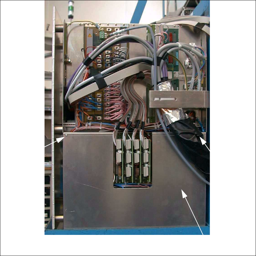
Fig. 2.8.2 Back of the Control Unit
Å On the back of the control unit, remove the cover over the SMP and AMS backplane (cover
007, see: Fig. 2.8.2): Undo 4 screws M2.5 internal serration T8.
Cover 007
Screw
Screw
SIPLACE S-23 HM 2 Retrofitting Instruct. S-23 HM to SW V 502.xx incl. RV6-DLM1 Head (Option)
07/01 Issue 2.8 Sequence: Modifying Hardware
81
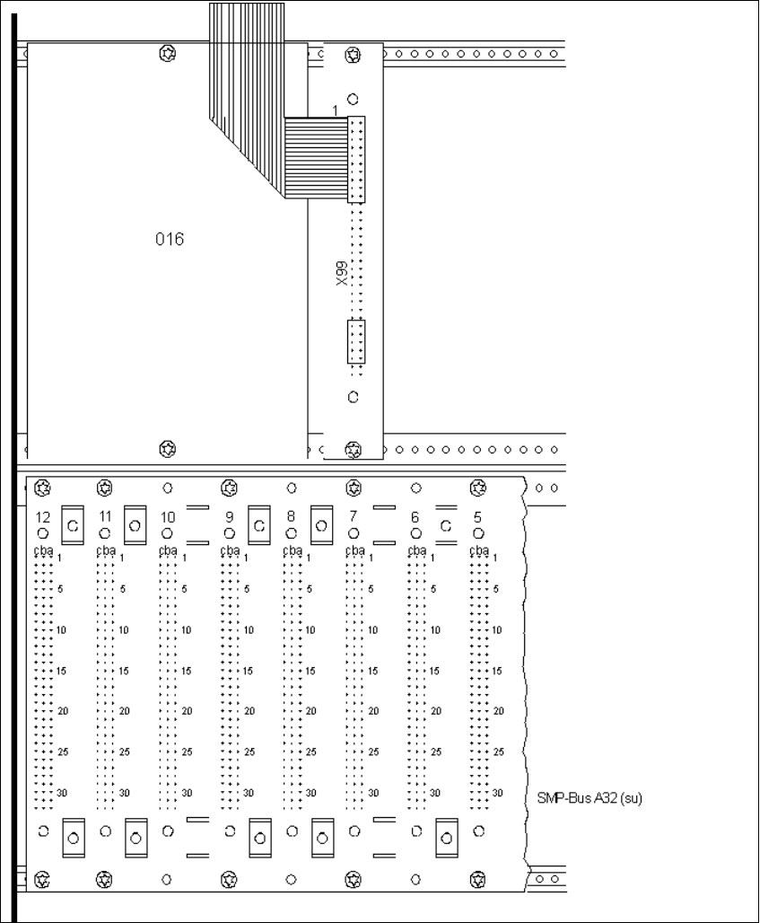
Fig. 2.8.3 View of the Backplane before Modification
Å Bend the ribbon cable on the 20-pin connector on plug connector X99 (above the SMP board
slot 7) back out the way and - if necessary - unplug the connector.
Å Remove the cover (016) above SMP board slot 8-12: 2 screws M2.5; internal serration T8, see:
Fig. 2.8.3.
2 Retrofitting Instruct. S-23 HM to SW V 502.xx incl. RV6-DLM1 Head (Option) SIPLACE S-23 HM
2.8 Sequence: Modifying Hardware 07/01 Issue
82
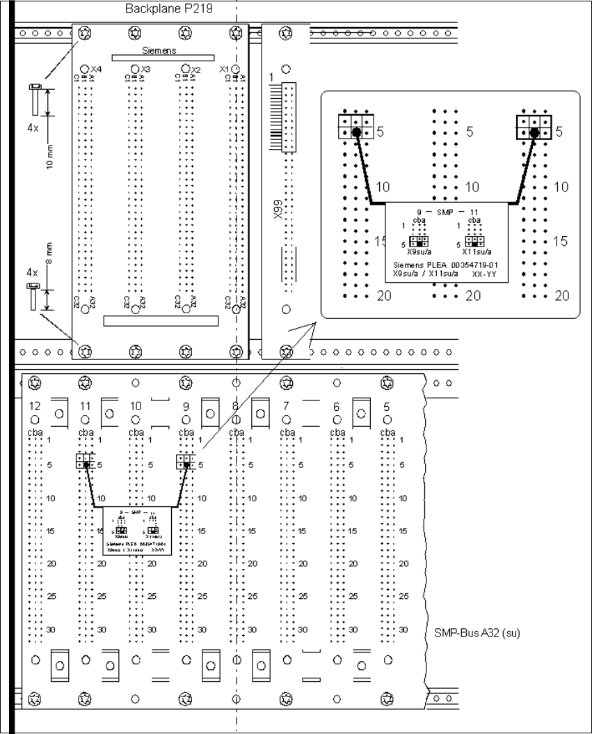
Fig. 2.8.4 Installing Backplane P219 and the Interrupt Connection
Å Install the new backplane P219 (from the retrofit kit) above the SMP board slots 8-11, see: fig-
ure above:
While doing so, align the backplane such that the board slots are in a line with those of the SMP
backplane. The connector designations X1-X4 on the back must be at the top.