XPM2_XPM3 Technical Ref Manual Conveyor1.pdf - 第11页
VI TRO NICS-SOLTEC REFLO W SOLDERING SYSTEMS Oc tober 10, 2008 11 XP M 2 / XPM 3 Technical Reference Manual Conv eyor Sy stem s CONVEYO R BELT , CHAI N & RAIL SERVICE REMOVE AND REPLACE C ONVEYOR MESH BELT 1. The m e…
VITRONICS-SOLTEC REFLOW SOLDERING SYSTEMS
October 10, 2008
10
XPM2 / XPM3 Technical Reference Manual Conveyor Systems
MBS COMBINATION EDGE RAIL AND BELT SYSTEM WITH METAL BAND SUPPORT
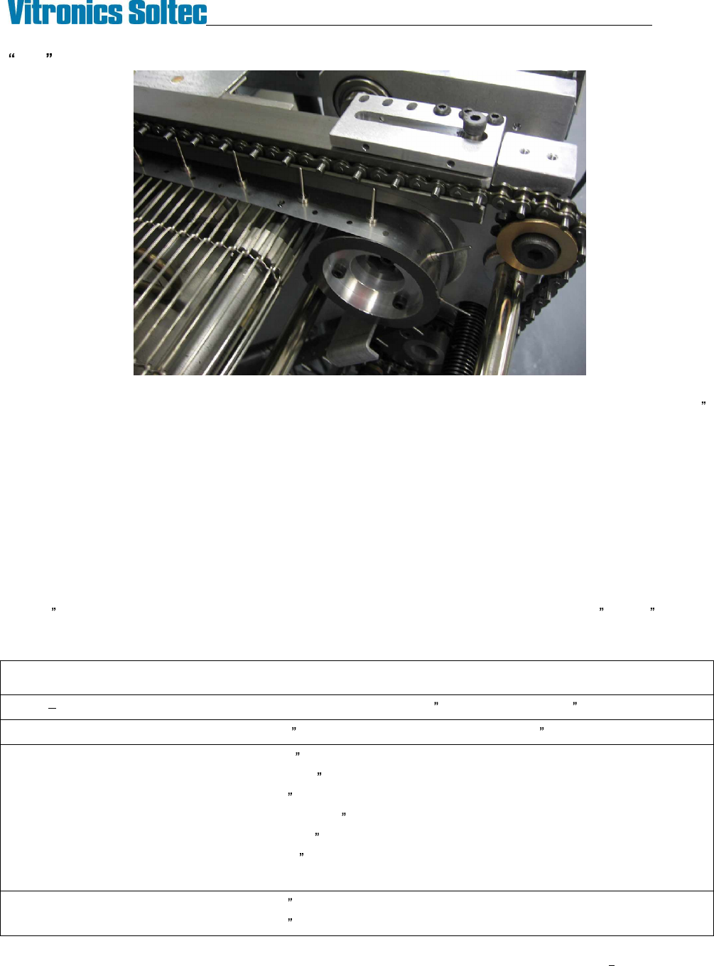
The Metal Band Support system consists of a combination rail and belt conveyor with a thin stainless steel band
having vertical pins riding on the mesh belt to support the middle of the PCB. They extend to approximately .025
below the surface of the edge rail chain pins where the PCB sits. The MBS pins can be parked between the
conveyor pins on the fixed rail chain, enabling the user to move the system out of the process lane when not
required. Although the MBS can be operated as a straight combo system by removing the MBS bands, due to
packaging constraints most of the components in the MBS conveyor ends are unique and will not interchange with
standard combo conveyor subassemblies.
This option is available with both manual and automatic positioning. When automatic positioning is specified both
the edge rail and MBS rails are computer controlled.
The MBS bands are considered consumables. The MBS bands must bend and straighten as they enter and exit
each of the four pulleys in the system and this flexing eventually causes cracks from metal fatigue. When this
happens the MBS bands must be replaced. The MBS bands were revised in January 2008 to improve service life.
The ¼ vent holes were removed and the thickness of the stainless steel was reduced from .006 to .005 to lower
the internal stresses that cause the cracking. The new MBS bands must not be mixed with the old bands as
premature failure of the new thinner bands will result.
MBS system general specifications:
Chain Both Edge Rails Rail ANSI #35 D1 (19 mm / 0.750 ) pitch chain with .186 long extended pin
Edge Rail parallel 0.5 mm / .020 maximum at feedscrews, 1.3 mm /.052 max total
MBS Pin Height 21.6 mm /.850
MBS Pin Diameter Ø1.52 mm /Ø.060
MBS Pin to fixed rail parallel 1.3 mm /.052 max total
MBS Pin height to edge rail +0 / -2.0 mm (+0 /-.08 )
MBS Pin tracking ± 1.3 mm / ± .050
MBS Pin height variation 0.76 mm / .030 maximum.
MBS park position MBS pins park between and completely within the fixed rail chain pins.
Auto Rail repeatability 0.1mm / .004 (edge rail and MBS axes)
Auto Rail set point accuracy 0.3mm / .012 max variation from command position (edge rail and MBS axes)
VITRONICS-SOLTEC REFLOW SOLDERING SYSTEMS
October 10, 2008
11
XPM2 / XPM3 Technical Reference Manual Conveyor Systems
CONVEYOR BELT, CHAIN & RAIL SERVICE
REMOVE AND REPLACE CONVEYOR MESH BELT
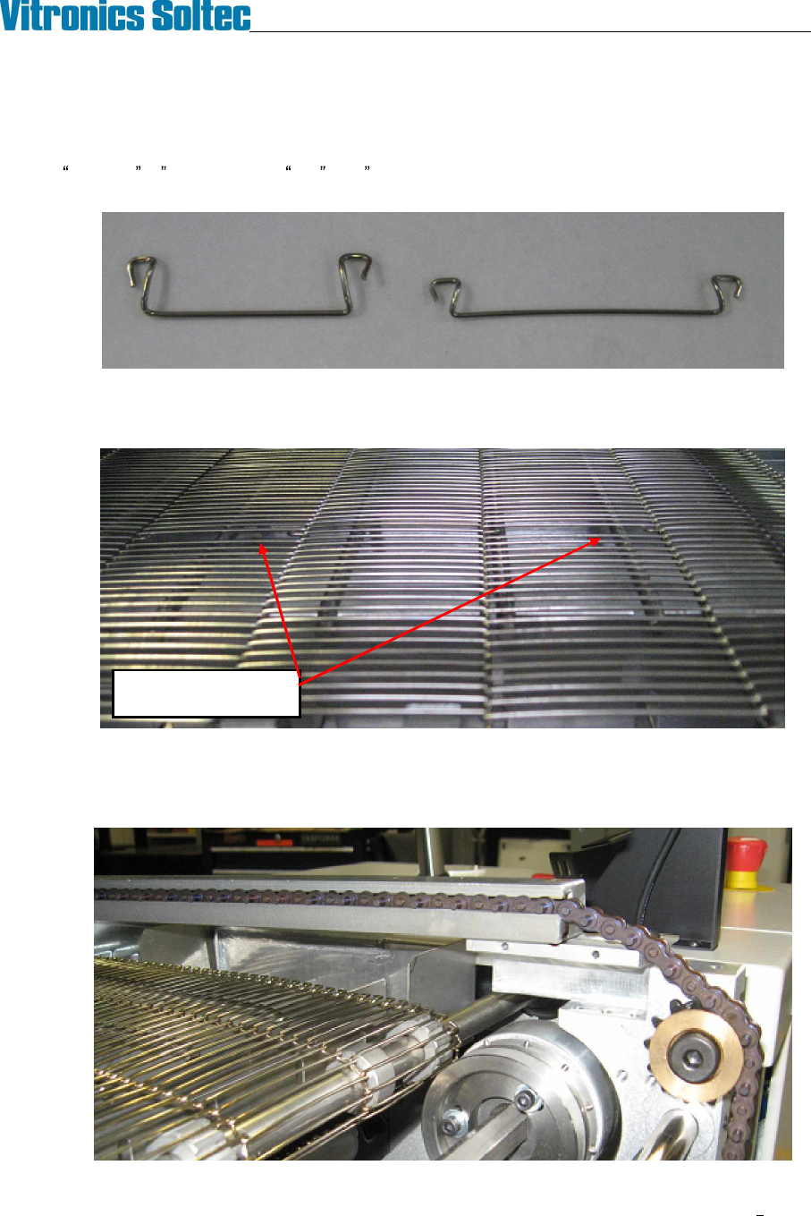
1. The mesh belts installed on XPM2 and XPM3 are available in several widths and in two different pitches,
standard ½ (12.7mm) and fine .286 (7.26mm). If splice clips are to be replaced verify that you have
the correct clips for the specific mesh belt.
2. Locate the splice point in the mesh belt by finding the double size 'holes' created by the splice clips. There
are four to six splice clips, depending on the width of the belt. For ease of access, turn the conveyor until
the splice point is positioned just inside the oven over one of the deck pans.
3. On conveyor systems with edge rails remove the chain guards from the rail ends near the splice clips,
remove the shoulder bolts that retain the rails in the capture brackets, and reposition the rails on top of the
capture brackets. It is not necessary to break the edge rail chains. Raising the rails will greatly improve
the working space above the mesh belt splice clips.
Double size holes at
Mesh Belt Splice Clips
VITRONICS-SOLTEC REFLOW SOLDERING SYSTEMS
October 10, 2008
12
XPM2 / XPM3 Technical Reference Manual Conveyor Systems
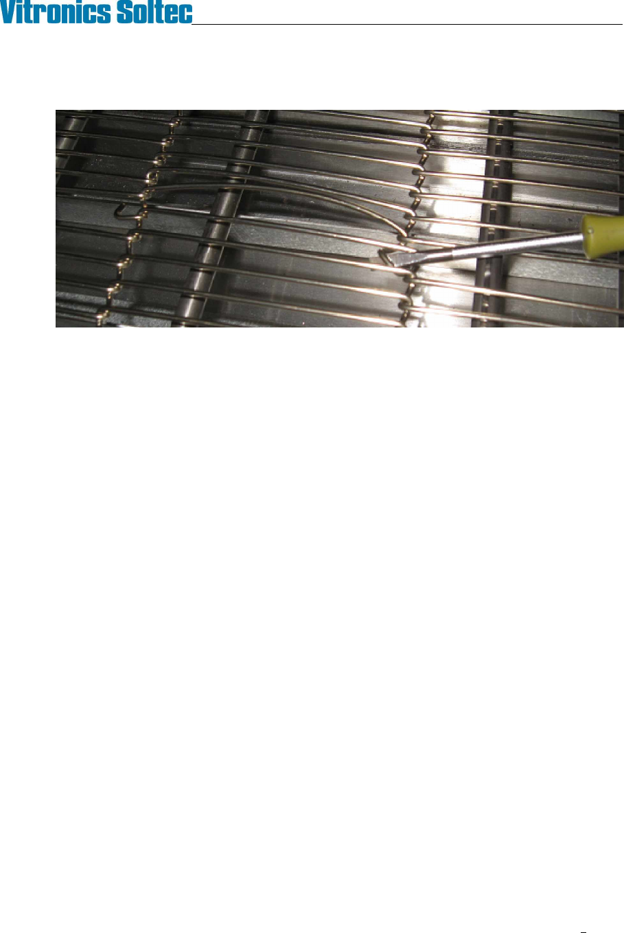
4. Start with the splice clip at one edge of the belt. Using a screwdriver or needle nose pliers unhook one
side of the clip from the belt. Rotate the clip through the belt to unhook its other end and remove it from
the belt.
5. Remove the remaining clips in the same manner to separate the mesh belt.
6. Installation is the reverse of removal. It may be helpful to temporarily bind the ends of the mesh belt
together with tie-wraps while installing the splice clips.