XPM2_XPM3 Technical Ref Manual Conveyor1.pdf - 第28页
VI TRO NICS-SOLTEC REFLO W SOLDERING SYSTEMS Oc tober 10, 2008 28 XPM 2 / XPM 3 Technical Reference M anual C onv ey or Sy stem s 4. At the of f -load end of the ov en, thread the X CS chain through th e sprock ets. Reco…
VITRONICS-SOLTEC REFLOW SOLDERING SYSTEMS
October 10, 2008
27
XPM2 / XPM3 Technical Reference Manual Conveyor Systems
INSTALL XCS CHAIN
Note: The XCS chain is custom manufactured as a pitch matched set with the fixed edge rail chain. Do not mix or
splice these chains. Always replace both chains as a set.
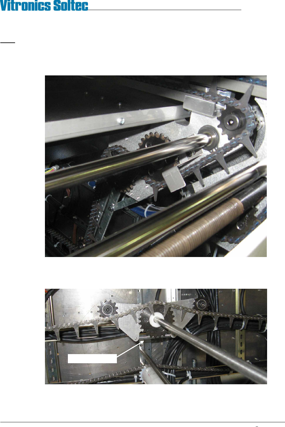
1. Feed the XCS chain into the offload end of the XCS rail until it reaches the opposite end of the machine.
2. Continue to thread the XCS chain over the sprockets at the on-load end then feed it back under the oven.
XCS chain routing typical, both ends
3. Thread the XCS chain through the tensioner trolley at the center of the return loop. The XCS tensioner
trolley is properly oriented when its extension spring is beneath the large sprocket.
Spring side down
VITRONICS-SOLTEC REFLOW SOLDERING SYSTEMS
October 10, 2008
28
XPM2 / XPM3 Technical Reference Manual Conveyor Systems
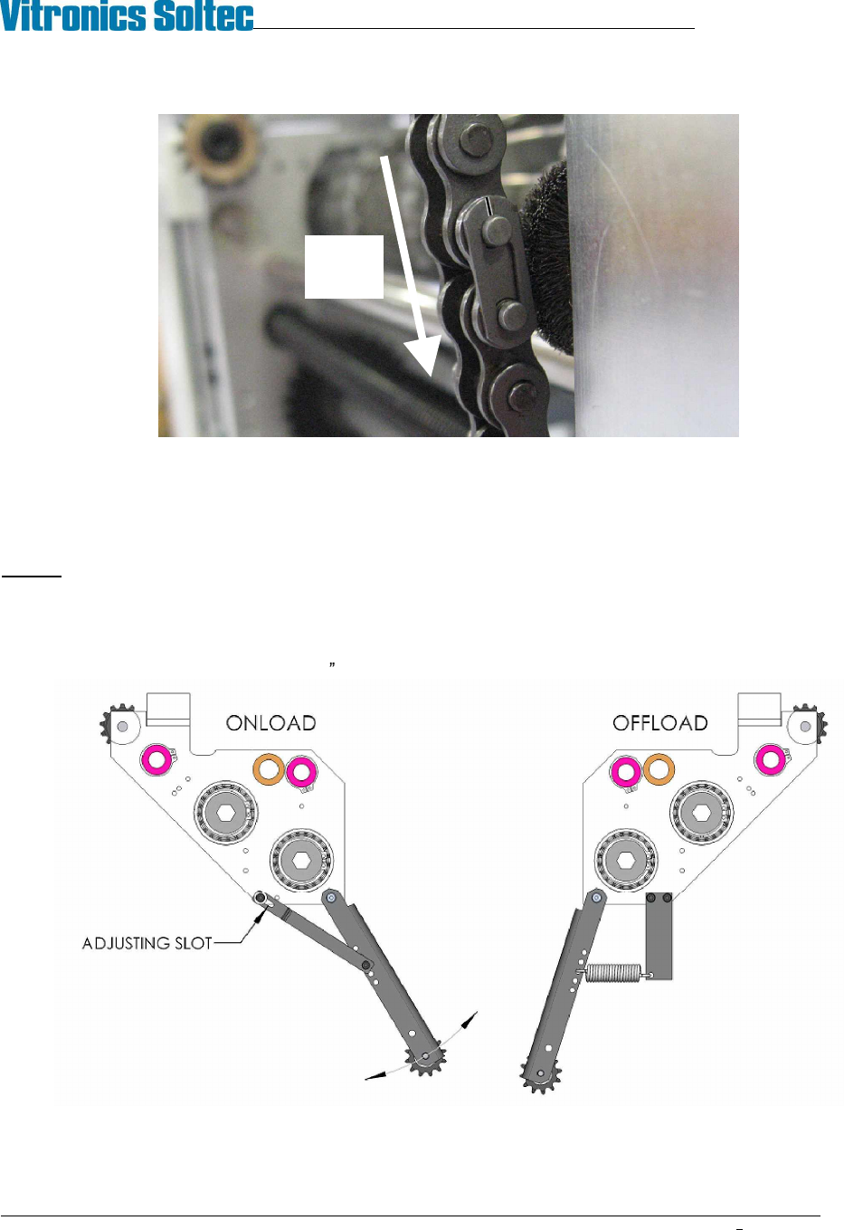
4. At the off-load end of the oven, thread the XCS chain through the sprockets. Reconnect the master link.
Make sure the closed end of the keeper clip is facing the direction of conveyor travel.
5. Check that the XCS chain is properly engaged with all of the sprockets and is not hung up or twisted
anywhere on top or underneath the oven.
SET XCS TENSION
Caution: Excessive tension in the XCS system will accelerate wear of the XCS chain.
1. Run the conveyor through several revolutions to ensure the XCS chain is properly settled.
2. The XCS tension is adjusted at the onload end of the machine by moving the XCS drop arm. The arm is
fixed by a slotted link. Use a 5/32 hex key and loosen the clamp screw to reposition the arm.
Direction
Of Chain
Travel
VITRONICS-SOLTEC REFLOW SOLDERING SYSTEMS
October 10, 2008
29
XPM2 / XPM3 Technical Reference Manual Conveyor Systems
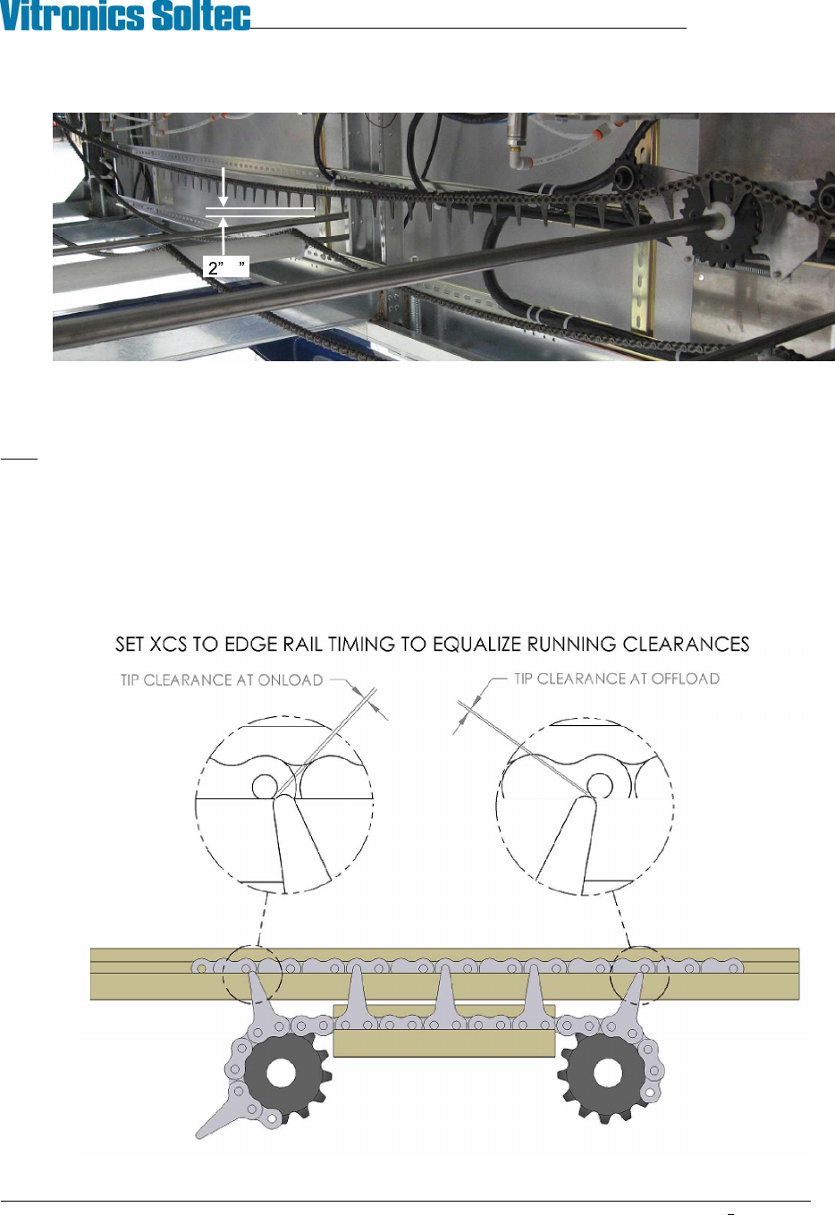
3. Adjust the XCS onload drop arm so that the lowest point of the XCS return loop is 2 to 3 inches (50 to
75mm) from touching at its lowest point.
SET XCS TIMING
Note: After extended service the XCS and edge rail chains may wear at different rates and this can affect their
pitch match. It may not be possible to park the XCS between the edge rail pins if excessive mismatch develops.
It is always better to set the XCS park position outside the edge rail pins if possible.
1. Position the XCS rail just outside of the fixed edge rail chain pins.
2. Examine the position of the XCS plates relative to the edge rail pins. Adjust the XCS timing to equalize
the available clearance between the tip of the XCS plates and edge rail pins as the XCS plates sweep in
and out of position at either end of the machine.
-3