XPM2_XPM3 Technical Ref Manual Conveyor1.pdf - 第43页
VI TRO NICS-SOLTEC REFLO W SOLDERING SYSTEMS Oc tober 10, 2008 43 XPM 2 / XPM 3 Technical Reference M anual C onv ey or Sy stem s RAIL W IDTH ADJUST OPERA T ION: Run the Manual rail adjust within the Ov en Con trol Progr…
VITRONICS-SOLTEC REFLOW SOLDERING SYSTEMS
October 10, 2008
42
XPM2 / XPM3 Technical Reference Manual Conveyor Systems
INITIAL SETUP
The following process is done at the time the oven is built. It should be required only after repair or service of the
Autolube System.
1) Locate the lubrication reservoir. ( see illustration above )
2) Fill the reservoir with the lubricant, Darmex (Vitronics-Soltec P/N 1227204). (Remove the cap and pour the
lubrication into the top of the reservoir.
3) Start the oven conveyor before you prime the lube system.
4) In the Oven Control Software click on the Oil Can Icon. This will bring up the Chain Lubrication utility dialog box.
Click on the box for Lube for Prime Period.
5) Priming the autolube system can take as much 6 hours depending on the size of the oven. The priming operation will
not shut-off automatically, therefore it MUST be monitored to prevent excess oil from dripping on the floor.
(During normal Manual & Auto Lube operations, the system does stop automatically)
NORMAL OPERATION
First, refer to Rail Chain Lubrication in the How Do I section under the Help menu in the oven software..
To perform a single manual lubrication of the conveyor chain:
Select manual lubrication in the Oven Control Software by clicking on the Oil Can Icon. This will bring up the Chain
Lubrication utility dialog box. Click on the box for Lube for Chain Distance. The conveyor chain will run, and lube oil will
be applied for two complete cycles of the chain(s).
For automatic lubrication of the conveyor chain on a regular basis:
Select automatic lubrication in the Oven Control Software by clicking on the Oil Can icon. This will bring up the Chain
Lubrication utility dialog box. Put a check mark in the box for Use Automatic Lubrication.
In automatic mode, the lubrication process does not interrupt oven processing. The chain will be lubed while there is
product in the oven.
ALARMS:
When the alarm count for lubrications has been reached a Low Oil Message will be displayed at the bottom of the
Operating Screen. Automatic or manual lubrication will not be permitted until the reservoir has been filled, and the alarm
reset. Reset the lubrication counter in the Oven Control Software by clicking on the Oil Can icon. This will bring up the
Chain Lubrication utility dialog box. Click on the box for Reset Lubrication Counter After Filling Tank.
This is the best time to adjust the cycles between lubes and/or the number of lubes before Low Oil Message
alarm.
VITRONICS-SOLTEC REFLOW SOLDERING SYSTEMS
October 10, 2008
43
XPM2 / XPM3 Technical Reference Manual Conveyor Systems
RAIL WIDTH ADJUST
OPERATION:
Run the Manual rail adjust within the Oven Control Program. NOTE: This operation may require a password.
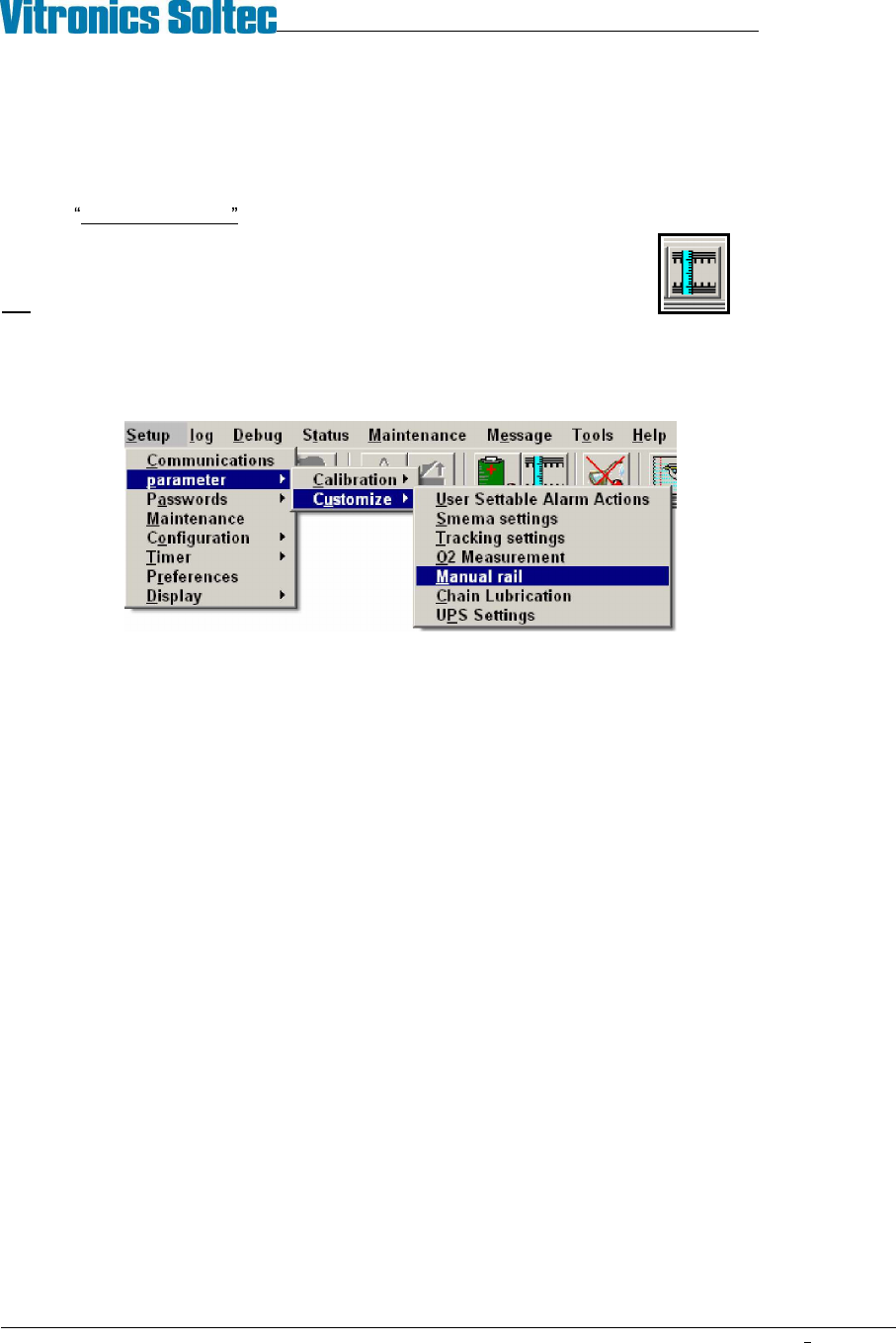
Manual rail adjust can be activated by clicking on the rail width adjust icon,
OR
by selecting Setup, Parameter, Customize, Manual Rail from the menu bar.
Test Procedure
1. Enable the manual rail adjust.
2. Select the rail to move if the oven has more then one rail adjust axis installed. The manual in/out rail switch is
a momentary 3 position rotary switch with a spring return to the center position and the center position is the
off position. None of the rails will move until the manual in/out switch is rotated and held in one direction.
The rail controller (A42) is a stand-alone controller that executes commands sent by the DI board through
RS485 communication. The rail controller (A42) only activates one of the rail direction relays (A1-K23 through
A1-K26) if the corresponding limit switch input is on or present. The rail controller (A42) activates the enable
output relay A1-K22 one second after one of the rail direction relays (A1-K23 through A1-K26) has been set.
3. Turn the rail in/out button in one direction. If the rail motor does not turn, turn the button in the other direction.
If the motor still does not turn, refer to the Oven Schematics and perform the following test procedure:
Disable the manual rail adjust.
Verify that the run status led on the rail controller (A42) is flashing. If the led is not flashing then there is a
problem with the rail controller board (A42).
Verify that the rail controller (A42) is firmly seated into the A1 board. If the run status led is not flashing
then the rail controller (A42) needs to be replaced.
If the run status led is flashing then verify that the cable from connector P3 on the front of the DI board to
connector P48 on the A1 board is installed correctly and that there are no loose wires on either connector.
Verify that the COM3 RXD and COM3 TXD leds on the front of the DI board flash periodically to indicate
that there is RS485 communication activity from the DI board to the rail controller (A42) and other boards
connected to the RS485 network.
The rail controller (A42) will not activate any of the rail output relays without RS485 communications being
initiated from the DI board.
Verify that the rail limit switch input status indicators are on on the rail controller (A42).

VITRONICS-SOLTEC REFLOW SOLDERING SYSTEMS
October 10, 2008
44
XPM2 / XPM3 Technical Reference Manual Conveyor Systems
Verify that each of the 2 manual rail in/out switch status indicator leds changes state on the rail controller
(A42) when the manual rail in/out switch is actuated in each direction. Each manual switch led status
indicator lights when the manual rail in/out switch is held on one direction.
If the rail in/out selections do not cause the corresponding status indicators to change on the rail controller
board to change, there MAY be a wiring error with the rail selector switch.
Verify that the jumpers are installed correctly on connector P62 on the A1 board. Also verify that there is
~130 VDC at connector P62 on the A1 board between pins 1 and 4.
Enable the manual rail switch.
Select Rail IN : A1-K24 or A1-K26 should energize depending on which rail is selected for movement.
A1-K22 should energize after a delay.
Select Rail OUT :A1-K23 or A1-K25 should energize depending on which rail is selected for movement.
A1-K22 should energize after a delay.
After the rail selection logic has been corrected, check to see that the wiring to the motor is correct.
Disable the manual rail adjust.
Enable the manual rail adjust.
Check the operation of both the in and the out adjust switch positions.
Disable the manual rail adjust.