XPM2_XPM3 Technical Ref Manual Conveyor1.pdf - 第50页
VI TRO NICS-SOLTEC REFLO W SOLDERING SYSTEMS Oc tober 10, 2008 50 XPM 2 / XPM 3 Technical Reference M anual C onv ey or Sy stem s DC DRIVE CALIBRATION (RA IL WIDT H ONLY) 1. Defini ti ons - A DC driv e is actually a DC v…

VITRONICS-SOLTEC REFLOW SOLDERING SYSTEMS
October 10, 2008
49
XPM2 / XPM3 Technical Reference Manual Conveyor Systems
2. The cable assembly (3156025) to the rotary encode is securely connected. Each rotary encoder has a finger
release on the connector to disconnect the 5pin cable assembly from the encoder.
3. Verify the continuity of the encoder cable assembly 3156025.
Wire Color A1-P46 or
A1-P47 Pin #
5 Pin Connector
on Encoder Pin #
Description
Red 1 4 5 VDC
Green 2 3 A channel output signal
White 3 5 B channel output signal
Black 4 1 0V dc common
Shield 5 No connection Shield
- - 2 Index output signal (not
used)
4. Monitor the output signals on the 5pin connector on the A1 board for each encoder in question.
5. The channel A and channel B outputs should transition from 0v to 5v while a lead screw is rotating and 5v
power should be present between pin 1(-) and pin 4(+) on the 5 pin connector on each encoder.
6. Verify that the plastic encoder disk is secured firmly on the lead screw by the set screw in the mounting collar.
7. Refer to the attached encoder manufactures instructions to verify the alignment of the encoder using the
alignment tool supplied by the manufacturer to properly align the plastic optical disk with the sensor assembly.
8. Replace the encoder assembly (1480801) if the output signals do not transition correctly or if the plastic optical
disk appears to be damaged.

VITRONICS-SOLTEC REFLOW SOLDERING SYSTEMS
October 10, 2008
50
XPM2 / XPM3 Technical Reference Manual Conveyor Systems
DC DRIVE CALIBRATION (RAIL WIDTH ONLY)
1.
Definitions-
A DC drive is actually a DC voltage amplifier. A small signal is sent to the drive and a large voltage is
sent to the motor. The typical DC drive uses an AC power source of 120 or 240 volts.
The set of controls found on a DC drive is:
A. Minimum speed adjust
B. Maximum speed adjust
C. IR comp
D. Torque
E. Signal
2.
What do the controls do?
A. Minimum speed adjust -- adjusts the minimum voltage output of the DC drive at the minimum-
input value. This value is typically 0 - 10% of the maximum input voltage.
B. Maximum speed adjust not used.
C. IR comp -- this adjusts the feedback circuit from the output of the DC drive. If the output voltage
drops, the IR comp circuit senses the drop, and more power is fed to the motor. This function is
preset to a value that covers 90% of all applications.
D. Torque -- this limits output current, and should only be adjusted by experienced people.
G. Signal -- signal adjust is found on DC drives which provide an option of being controlled by a
computer. If the DC drive is adjusted by a speed control potentiometer, signal or signal adjust has
no function.
Note: A DC drive with computer control will have a signal/manual selector switch or jumper. If the input
does not match the input selected, the DC drive will not operate correctly.
If a computer controls the DC drive, the maximum adjustment potentiometer will have no function.
3. Additional useful information
A. Always recalibrate when any component of a control system is changed.
B. Conveyor speed can be calibrated to specific requirements. This takes practice, but can yield
greater speed accuracy.
C. The conveyor speed should be measured with a stopwatch every sixty days.
D. Motor brushes wear out.
E. Calibration values may change with the age of the system.
F. Always record the adjusting potentiometer settings before replacing or calibrating a DC drive.
G. When replacing a DC drive, record the potentiometer settings; draw a sketch of the wire hookups;
make sure all wires have labels.
VITRONICS-SOLTEC REFLOW SOLDERING SYSTEMS
October 10, 2008
51
XPM2 / XPM3 Technical Reference Manual Conveyor Systems
CALIBRATION PROCEDURE FOR DC DRIVE BOARD (rail width only)
Tools required:
Multimeter (auto-ranging)
Small non-metallic screwdriver
Stop watch or other device to time conveyor movement
Before connecting the power supply:
1. Set the Jumper to signal .
2. Set the MAX SPEED pot to full counter-clockwise.
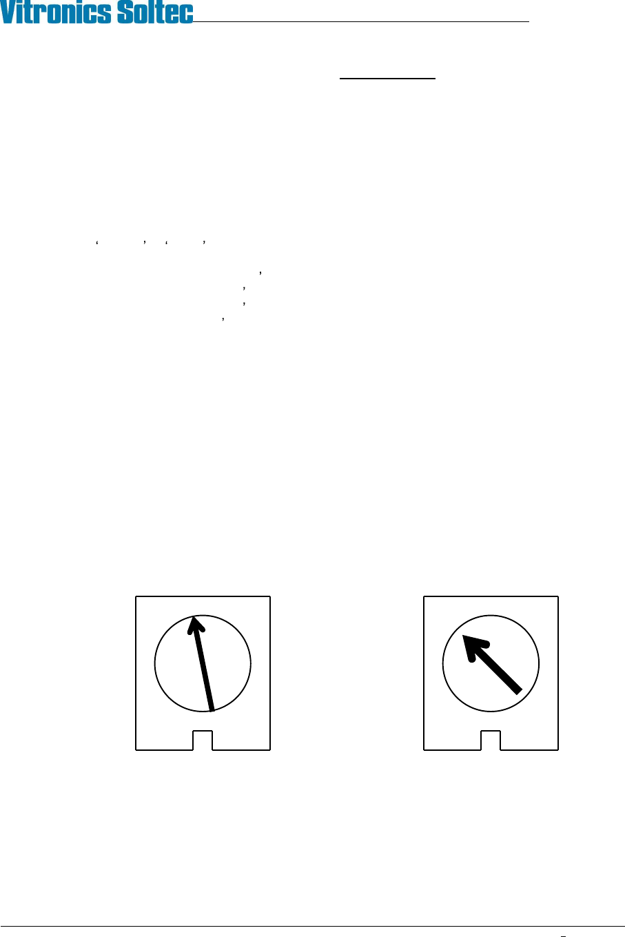
3. Set the MIN SPEED pot to the 10 o clock position.
4. Set the IR COMP pot to the 12 o clock position.
5. Set the TORQUE pot to the 10 o clock position.
6. Set the signal Pot to the 12 o clock position.
With the power supply connected:
1.
Set the multimeter to VOLTS AC and measure the input voltage to the control. If the voltage is less
than 108V or greater than 132V disconnect the power supply and correct the supply voltage problem.
2.
Disconnect the multimeter and set to measure VOLTS DC. Attach leads to the motor side of the
control.
3.
Log in to the oven software with the master password. Under Vitronics Soltec, Advanced, Service Mode
Testing, go to the Conveyor tab. Type in a percentage number (0-100) in the box for Conveyor%, then
select either Move in min speed or Move out min speed. Adjust the MIN speed pot so the conveyor is just
barely moving. When done select Stop Rail.
4.
Select either Move in Max speed or Move out Max Speed. Adjust the Signal Adjust pot until the
conveyor movement speed is equal to 5 inches per minute. When done select Stop Rail and exit this
function.
5.
Verify that the width adjust hits setpoint. If not, the minimum speed may be set too low or too high.
IR COMP TORQUE
MINARIK DRIVE POTENTIOMETER SETTINGS