XPM2_XPM3 Technical Ref Manual Conveyor1.pdf - 第9页
VI TRO NICS-SOLTEC REFLO W SOLDERING SYSTEMS Oc tober 10, 2008 9 XPM 2 / XPM 3 Technical Reference M anual C onv ey or Sy stem s XCS EDGE RAIL W ITH EXTRU DED C ENTER SUPPORT SYSTEM The eX trud e d Center Supp ort sys te…
VITRONICS-SOLTEC REFLOW SOLDERING SYSTEMS
October 10, 2008
8
XPM2 / XPM3 Technical Reference Manual Conveyor Systems
RAIL-ONLY EDGE / RAIL CONVEYOR SYSTEM
The edge / rail conveyor system (shown below) permits single or double sided surface mount printed circuit boards
to be processed through the oven. The standard chain conveyor carries circuit boards on 0.185 inch (4.75mm)
long pins extending from the chains. This conveyor system provides a convenient interface to other equipment in
the production line. Some Ovens have two sets of rails and chains (Dual Rail) for the processing of two PCBs at
the same time.
ADJUSTMENT LEAD SCREWS
PROCESS TUNNEL
Edge Conveyor Rails
Edge / rail conveyor system.
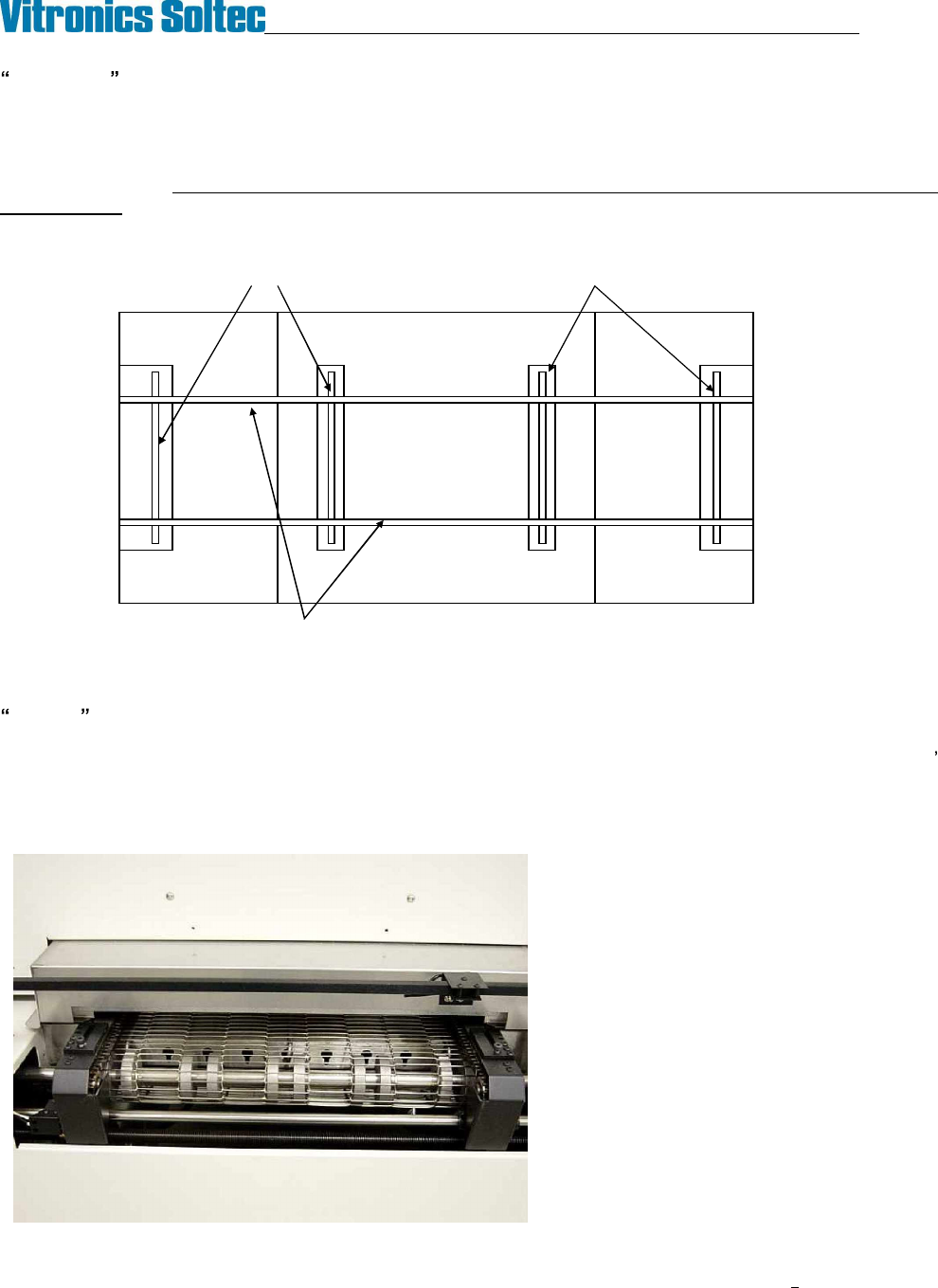
COMBO COMBINATION CONVEYOR SYSTEM
The combination belt/rail conveyor has both the edge rail and a mesh belt. The mesh belt is approximately 7/8
(22mm) below the edge rail conveyor, and both conveyors are driven together. The belt conveyor is shorter than
the outside edge of the machine with the sheet metal covers on, and shorter than the end of the rails with chain
guards installed.
Approximately 3 inches between end
of belt and end of rail conveyor (both
ends).
VITRONICS-SOLTEC REFLOW SOLDERING SYSTEMS
October 10, 2008
9
XPM2 / XPM3 Technical Reference Manual Conveyor Systems
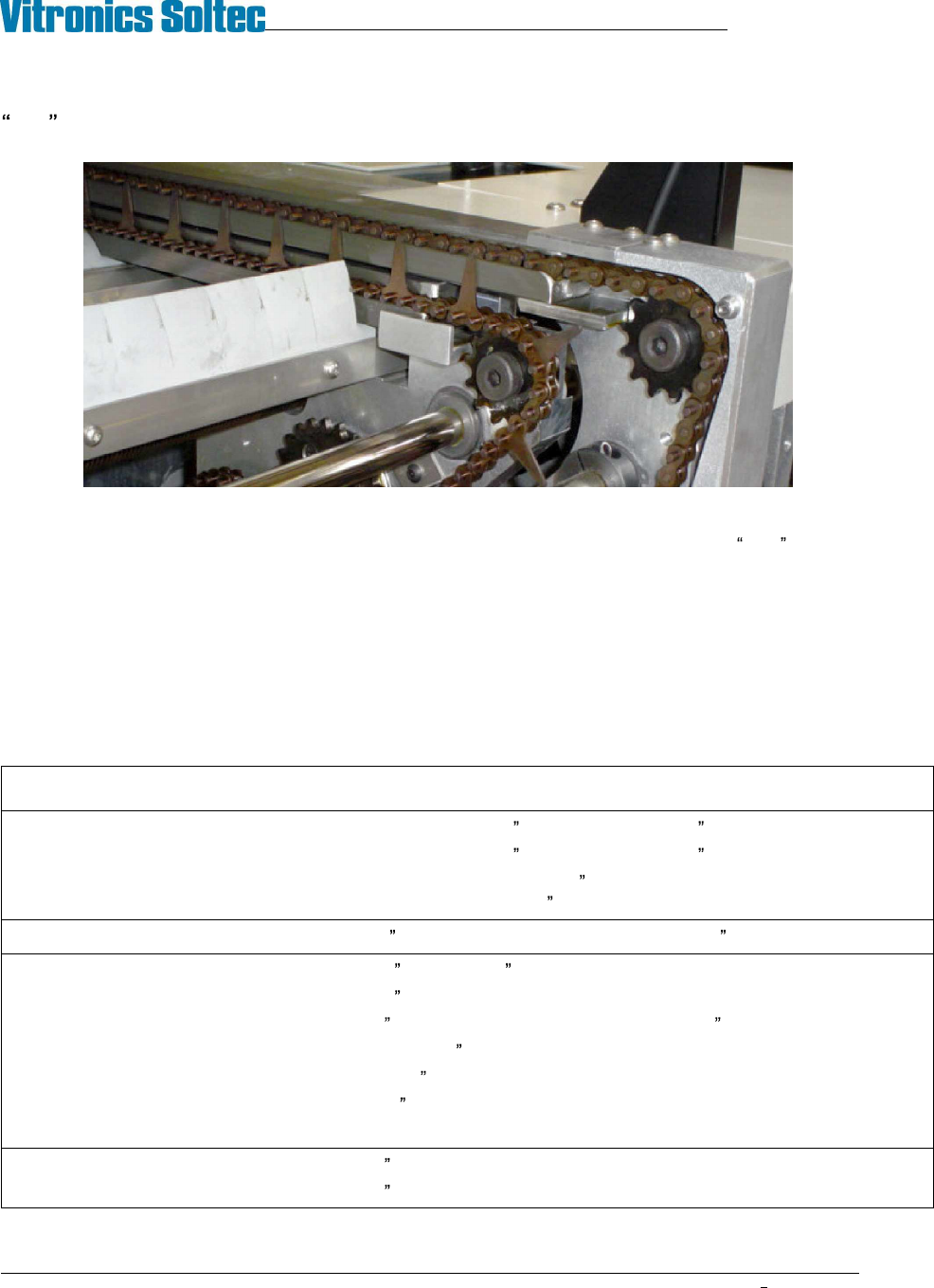
XCS EDGE RAIL WITH EXTRUDED CENTER SUPPORT SYSTEM
The eXtruded Center Support system consists of an additional rail extrusion and a special XCS chain with
extended side plates that supports the middle of the PCB to prevent warping. The XCS plates extend to the same
height as the top of the edge rail chain pins where the PCB sits. The XCS chain can be parked between the
conveyor pins on the fixed rail chain, enabling the user to move the system out of the process lane when not
required. After a period of time both the conveyor chains and the XCS chain will stretch, and it may not be
possible to park the XCS between the fixed rail pins. When this happens, the fixed edge rail chain and the XCS
chain must be replaced as a matched set.
This option is available with both manual and automatic positioning. When automatic positioning is specified both
the edge rail and XCS rails are computer controlled.
XCS system general specifications:
Chain - Fixed Edge Rail ANSI #35 D3 (9.5mm / 0.375 ) pitch chain with .186 long extended pin
Chain - Moveable Edge Rail ANSI #35 D1 (19 mm / 0.750 ) pitch chain with .186 long extended pin
Chain - XCS Special ANSI #35 D3 (9.5mm / 0.375 ) pitch chain with extended side
plates installed on 38.1mm / 1.50 pitch spacing.
Edge Rail parallel 0.5 mm / .020 maximum at feedscrews, 1.3 mm /.052 max total
XCS Chain Plate Height 22.2 mm /.875 (17mm / .67 directly over XCS rail)
XCS Chain Plate Width 1.25 mm /.050
XCS rail to fixed rail parallel 0.5 mm /.020 maximum at feedscrews, 1.3 mm /.052 max total
XCS height to edge rail +0 / -2.0 mm (+0 /-.08 )
XCS chain plate tracking ± 1.3 mm / ± .050
XCS plate height variation 0.15 mm / .006 maximum.
XCS park position XCS plates park between* and completely within the fixed rail chain pins.
Auto Rail repeatability 0.1mm / .004 (edge rail and XCS axes)
Auto Rail set point accuracy 0.3mm / .012 max variation from command position (edge rail and XCS axes)
* After extended service the XCS and edge rail chains may wear at different rates and this can affect their pitch
match. If excessive mismatch develops it may no longer be possible to park the XCS between the edge rail pins.
VITRONICS-SOLTEC REFLOW SOLDERING SYSTEMS
October 10, 2008
10
XPM2 / XPM3 Technical Reference Manual Conveyor Systems
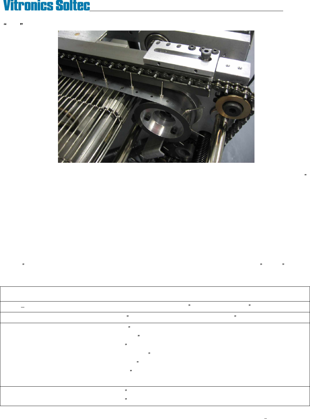
MBS COMBINATION EDGE RAIL AND BELT SYSTEM WITH METAL BAND SUPPORT
The Metal Band Support system consists of a combination rail and belt conveyor with a thin stainless steel band
having vertical pins riding on the mesh belt to support the middle of the PCB. They extend to approximately .025
below the surface of the edge rail chain pins where the PCB sits. The MBS pins can be parked between the
conveyor pins on the fixed rail chain, enabling the user to move the system out of the process lane when not
required. Although the MBS can be operated as a straight combo system by removing the MBS bands, due to
packaging constraints most of the components in the MBS conveyor ends are unique and will not interchange with
standard combo conveyor subassemblies.
This option is available with both manual and automatic positioning. When automatic positioning is specified both
the edge rail and MBS rails are computer controlled.
The MBS bands are considered consumables. The MBS bands must bend and straighten as they enter and exit
each of the four pulleys in the system and this flexing eventually causes cracks from metal fatigue. When this
happens the MBS bands must be replaced. The MBS bands were revised in January 2008 to improve service life.
The ¼ vent holes were removed and the thickness of the stainless steel was reduced from .006 to .005 to lower
the internal stresses that cause the cracking. The new MBS bands must not be mixed with the old bands as
premature failure of the new thinner bands will result.
MBS system general specifications:
Chain Both Edge Rails Rail ANSI #35 D1 (19 mm / 0.750 ) pitch chain with .186 long extended pin
Edge Rail parallel 0.5 mm / .020 maximum at feedscrews, 1.3 mm /.052 max total
MBS Pin Height 21.6 mm /.850
MBS Pin Diameter Ø1.52 mm /Ø.060
MBS Pin to fixed rail parallel 1.3 mm /.052 max total
MBS Pin height to edge rail +0 / -2.0 mm (+0 /-.08 )
MBS Pin tracking ± 1.3 mm / ± .050
MBS Pin height variation 0.76 mm / .030 maximum.
MBS park position MBS pins park between and completely within the fixed rail chain pins.
Auto Rail repeatability 0.1mm / .004 (edge rail and MBS axes)
Auto Rail set point accuracy 0.3mm / .012 max variation from command position (edge rail and MBS axes)