XPM2_XPM3 Technical Ref Manual Conveyor1.pdf - 第40页
VI TRO NICS-SOLTEC REFLO W SOLDERING SYSTEMS Oc tober 10, 2008 40 XPM 2 / XPM 3 Technical Reference M anual C onv ey or Sy stem s COMPUTER CONTROLLED EDGE-RA IL LUBRICA T ION Computer Controlled Edge-R ail Lubrication is…
VITRONICS-SOLTEC REFLOW SOLDERING SYSTEMS
October 10, 2008
39
XPM2 / XPM3 Technical Reference Manual Conveyor Systems
DRIVE MOTOR SERVICE & REPLACEMENT
Conveyor Drive Motor Replacement - MOTOR LOCATION
There are only two locations for the conveyor motor on all Vitronics-Soltec Reflow Ovens. On an oven with a left
To right conveyor, the motor assembly is in the front right corner of the oven. On an oven with a right to left
conveyor system, the motor assembly is on the front left corner of the oven.
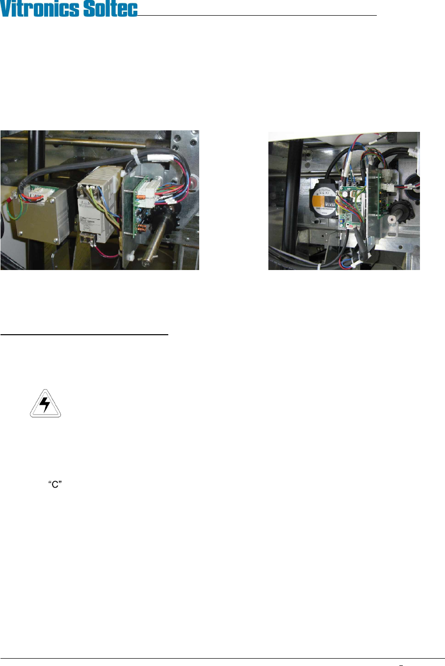
Integra Motor Oriental Motor
CONVEYOR MOTOR REPLACEMENT
To remove/replace the Conveyor Drive Motor:
1. Open the Hood
2. Turn off the U.P.S. and disconnect all power from the oven.
3. Remove the sheet metal at the exit end of the end the oven to gain clear access to the motor and
components.
4. Remove the G5 power supply
5. Unplug the cable from the motor.
6. The Motor is attached to a mounting plate with four bolts. That plate is mounted with four bolts on the Oven
Frame Channel. Loosen the four bolts and slide the plate to the exit end of the oven. This will allow the
Chain to be removed from the Drive Sprocket without removing the Master Link from the Chain.
7. While supporting the Motor, remove the four bolts. Remove the motor, mounting plate and sprockets from the
Oven.
8. Rotate the Motor to permit access to the setscrews that secure the drive sprocket to the Motor Drive Shaft.
Loosen the setscrews and remove the sprocket, then remove the Motor from the mounting plate.
9. Install the new motor and drive sprocket on the mounting plate.
Reverse steps 7 through 1 to replace the Conveyor Drive Motor
Left to Right Conveyor
VITRONICS-SOLTEC REFLOW SOLDERING SYSTEMS
October 10, 2008
40
XPM2 / XPM3 Technical Reference Manual Conveyor Systems
COMPUTER CONTROLLED EDGE-RAIL LUBRICATION
Computer Controlled Edge-Rail Lubrication is:
!
Standard, (installed on all ovens)
)
An option, (NOT installed on all ovens)
DESCRIPTION:
The edge-rail lubrication system is designed to improve the lifetime of the rail chain conveyor by periodically
applying lubrication to the chain during oven operation.
Two modes of lubrication are available, automatic and manual. Systems with automatic chain lubrication are also
capable of performing manual chain lubrication, initiated by the operator, through the Oven Operation Program.
OPERATION:
fi Following the enabling of an output from the controller, the system pumps oil from the reservoir, through
tubing, to stainless steel brush/wheels which are touching the chain and the oil is applied to the chain.
fi It is the user s responsibility to ensure that this reservoir is always filled with the required lubricant. The
system generates a warning message when it calculates that the oil in the reservoir is getting low.
fi The lubricant type is DARMEX OIL # 773ND
During the lubrication process, the oil is applied for two complete cycles of the chain. The user may determine the
number of chain cycles between automatic lubrications. 275 is the default number.
The number of complete lubrications held within one reservoir is set to the factory default of 50. The system will
display a warning whenever it calculates that the reservoir level is getting low when the number of lubrication
cycles that have occurred reaches the tank count number in the lubrication setup screen. Since the amount of oil
dispensed in one application is system dependent, the number of complete lubrications is best found by trial and
error.
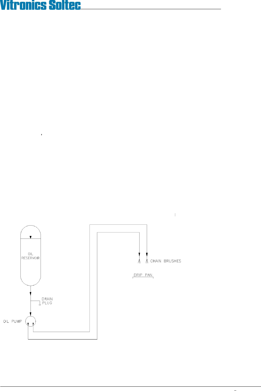
Construction:
The Auto Chain Lube System
consists of a 1 quart
polypropylene oil reservoir,
drain plug, electrically powered
pump, tubing for oil
distribution, and two stainless
steel brushes for the
application of lubricating oil
directly to both oven conveyor
chains.
Auto Chain Lube System Schematic
VITRONICS-SOLTEC REFLOW SOLDERING SYSTEMS
October 10, 2008
41
XPM2 / XPM3 Technical Reference Manual Conveyor Systems
AUTO CHAIN LUBE TANK/PUMP ASSY
Operation:
The lubrication pump motor speed is 1 rpm with a displacement of .06cc per stroke (rev). The pump will output 1
drop of oil for each minute of conveyor chain travel. The oil is sent through the oil distribution hoses up to the
stainless steel brushes.
Priming:
Priming the system through the software can be very time consuming because of the low displacement of the
pump...
Priming should only be necessary after:
1. Servicing the auto lube system
2. The reservoir has been allowed to run dry and air has been pumped into the lube lines
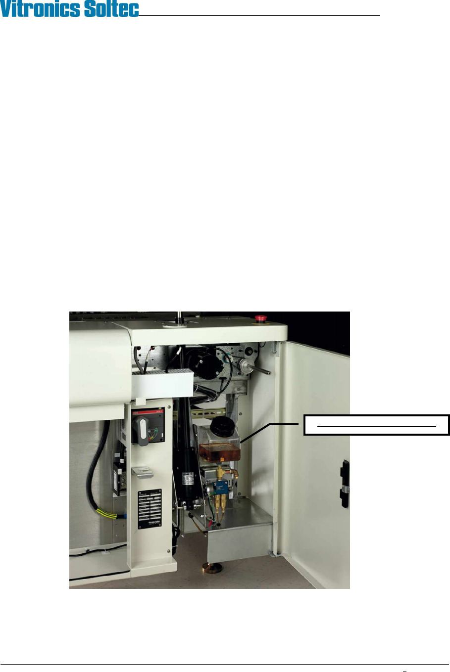
Location:
The Lubrication Tank-Pump Assembly is mounted to the frame at the front of the oven, inside the utility cabinet, at
the exit end of the oven.
CHAIN LUBE RESERVOIR