XPM2_XPM3 Technical Ref Manual Conveyor1.pdf - 第17页
VI TRO NICS-SOLTEC REFLO W SOLDERING SYSTEMS Oc tober 10, 2008 17 XPM 2 / XPM 3 Technical Reference M anual C onv ey or Sy stem s 5. Lif t the rail s up into the hang er bars and s ecure w i th barrel nuts and t hrust w …
VITRONICS-SOLTEC REFLOW SOLDERING SYSTEMS
October 10, 2008
16
XPM2 / XPM3 Technical Reference Manual Conveyor Systems
INSTALL RAILS
1. Visually inspect the rails for straightness and wear or damage to the chain guide surfaces.
2. Slide the appropriate number of rail clamps on each rail extrusion. Check that each clamp is properly
seated on the rail. Do not tighten the rail clamps, their position will be adjusted later in the installation.
3. Place the rail and clamp assemblies in the tunnel. Slide the rails under the hanger bars and place the
ends of the rails into the conveyor end plates. Position the rails all the way toward the onload end of the
machine and install the shoulder bolts through the capture brackets to retain the rails in the end plates.
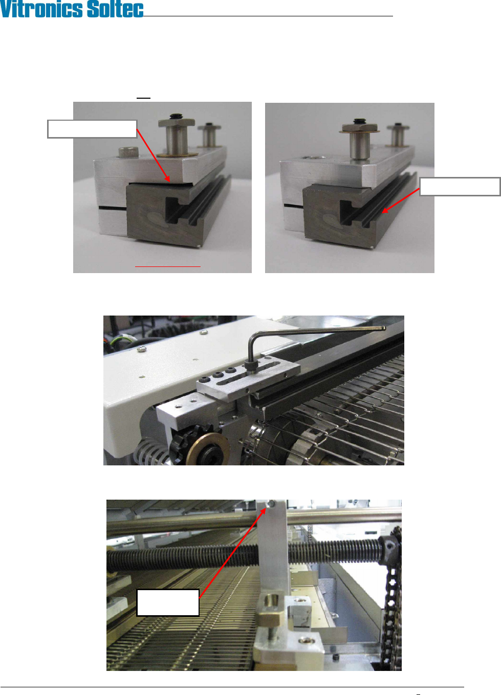
4. Check that all hanger bars are in line above the rail clamps. The pinch bolts in the fixed rail hangers
should be left loose.
Leave pinch
bolt loose
INCORRECT ! CORRECT
Clamp not seated
Check for wear
VITRONICS-SOLTEC REFLOW SOLDERING SYSTEMS
October 10, 2008
17
XPM2 / XPM3 Technical Reference Manual Conveyor Systems
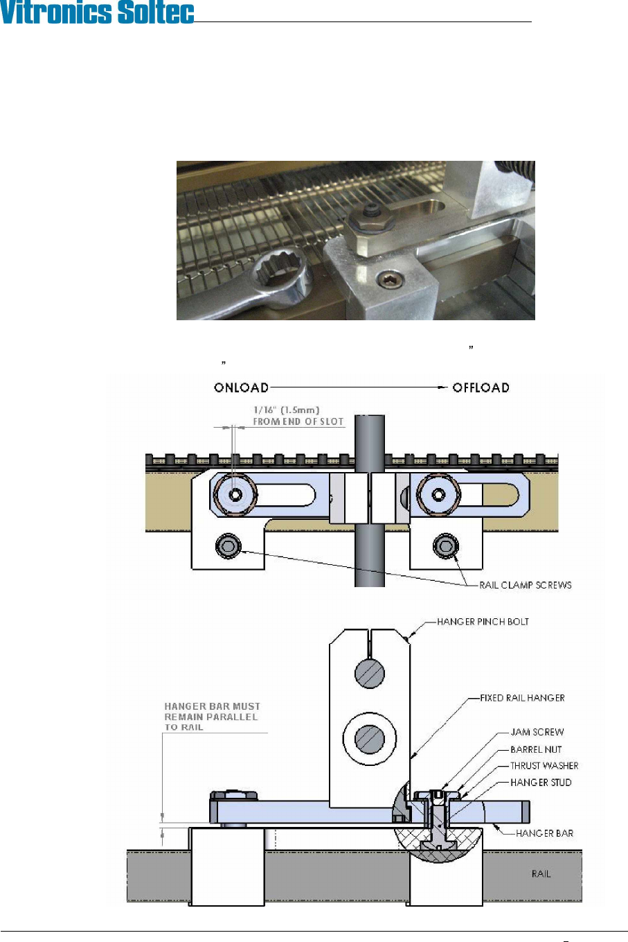
5. Lift the rails up into the hanger bars and secure with barrel nuts and thrust washers. Do not force the nuts
into the hanger slots, they should turn all the way down by hand. Excessive force will gall the stainless
steel nuts and bar slots preventing free movement of the rail for thermal growth. If the barrel nuts bind,
stop and check alignment of the hanger with the rail. Tighten the barrel nuts until they bottom out against
the top of the rail clamps. Make sure that the jam screw in the top of the barrel nut is backed off enough
so that it does not stop the barrel nut before it is fully seated. Once the barrel nuts are tightened tighten
the jam screws.
6. Visually check that all hangers are resting level with the rail, then slide each rail hanger clamp toward the
onload end of the machine until the barrel nuts are approximately 1/16 (1.5mm) from the end of the
hanger bar slots. Use a 3/16 hex key to tighten the rail clamp screws to lock the clamps to the rails.
VITRONICS-SOLTEC REFLOW SOLDERING SYSTEMS
October 10, 2008
18
XPM2 / XPM3 Technical Reference Manual Conveyor Systems
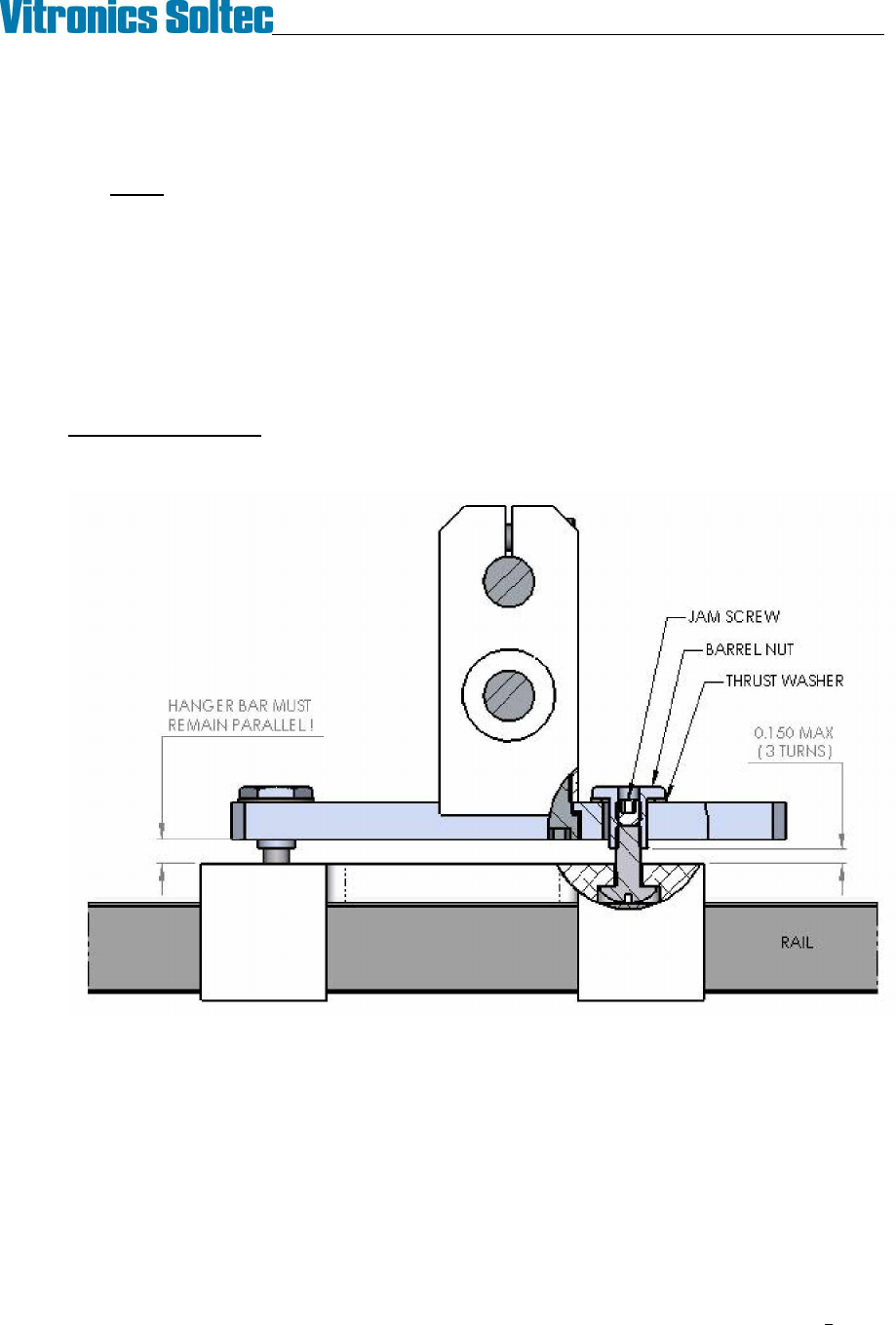
7. Turn the thrust washer under each barrel nut by hand to verify that all of the nuts are in contact with the
hanger bars.
NOTE: It is very important to the function of the hanger system that all barrel nuts carry
some load. The installed height of the gantries can vary slightly due to tolerance stack-
ups in the oven sheet metal subassemblies so it is sometimes necessary to adjust the
height of the rail in the hangers. Equal height of all hangers is especially important on
1240 machines where two pairs of supports are only separated by one cell.
If adjustment is needed use the intermediates as the known height reference and make adjustments to the
hangers at the gantries.
To lower the rail height in a hanger loosen the jam screws then unscrew both barrel nuts an equal amount,
up to three full turns of the barrel nuts maximum.