XPM2_XPM3 Technical Ref Manual Conveyor1.pdf - 第20页
VI TRO NICS-SOLTEC REFLO W SOLDERING SYSTEMS Oc tober 10, 2008 20 XP M 2 / XPM 3 Technical Reference Manual Conv eyor Sy stem s A LI GN AN D PA RA LLEL EDGE R AILS ALIGN FIXED RAIL 1. The f ix ed rail is adjus ted straig…
VITRONICS-SOLTEC REFLOW SOLDERING SYSTEMS
October 10, 2008
19
XPM2 / XPM3 Technical Reference Manual Conveyor Systems
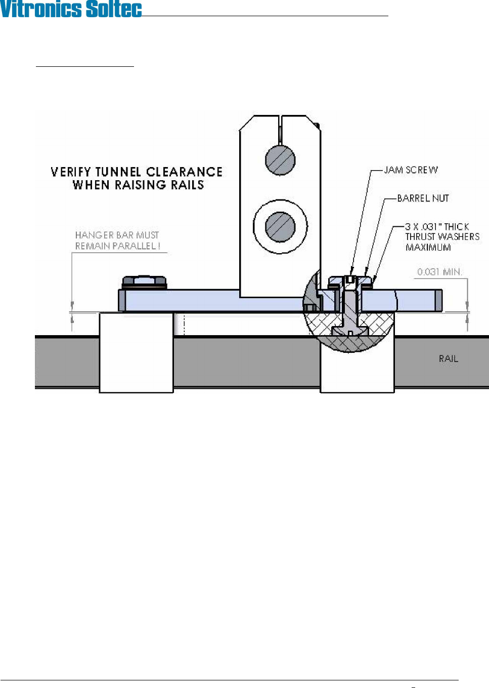
To raise the rail height add one or two thrust washers under both barrel nuts, fully seat the nuts, then
unscrew them equal amounts to fine tune as necessary. There is only enough clearance for two additional
thrust washers, do not attempt to use more than three.
When adjustments are complete tighten the jam screws to lock the barrel nuts in place.
8. After aligning the fixed rail and setting parallel (see next section), temporarily remove the fixing screws
from the onload end capture brackets and check for free movement of both rails in the hanger brackets.
The barrel nuts should slide in the hanger bar slots without catching or tending to twist the hanger
assembly around its mount.
VITRONICS-SOLTEC REFLOW SOLDERING SYSTEMS
October 10, 2008
20
XPM2 / XPM3 Technical Reference Manual Conveyor Systems
ALIGN AND PARALLEL EDGE RAILS
ALIGN FIXED RAIL
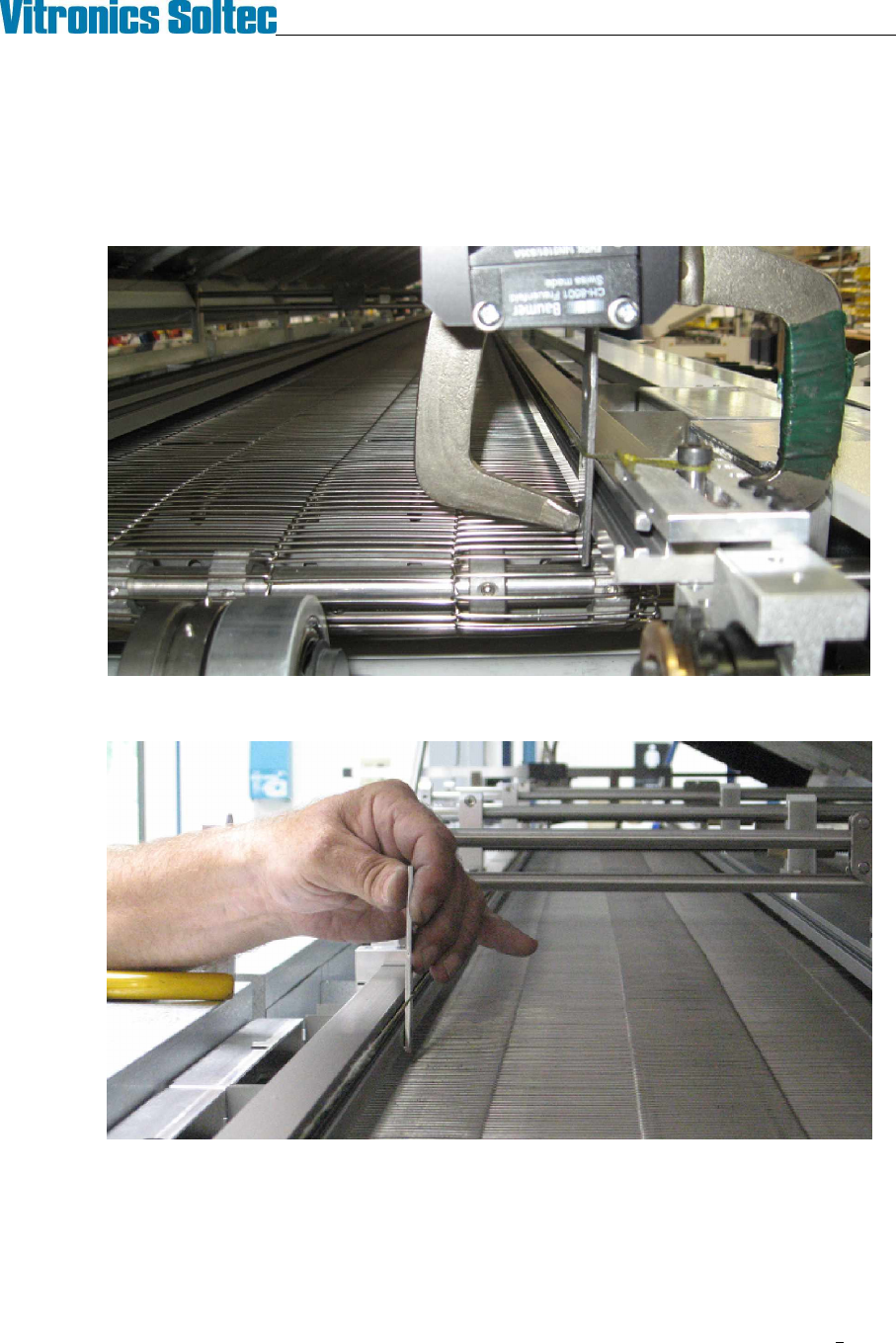
1. The fixed rail is adjusted straight using a string and three small metal plates of identical thickness.
2. Clamp one of the small plates to each end of the fixed rail and stretch a string between them.
3. Use the third plate to gauge the position of the rail at each gantry and intermediate.
4. Adjust the position of the intermediate and gantry fixed rail hangers on the cross bars to straighten the rail
relative to the string.
VITRONICS-SOLTEC REFLOW SOLDERING SYSTEMS
October 10, 2008
21
XPM2 / XPM3 Technical Reference Manual Conveyor Systems
SET LANE PARALLEL
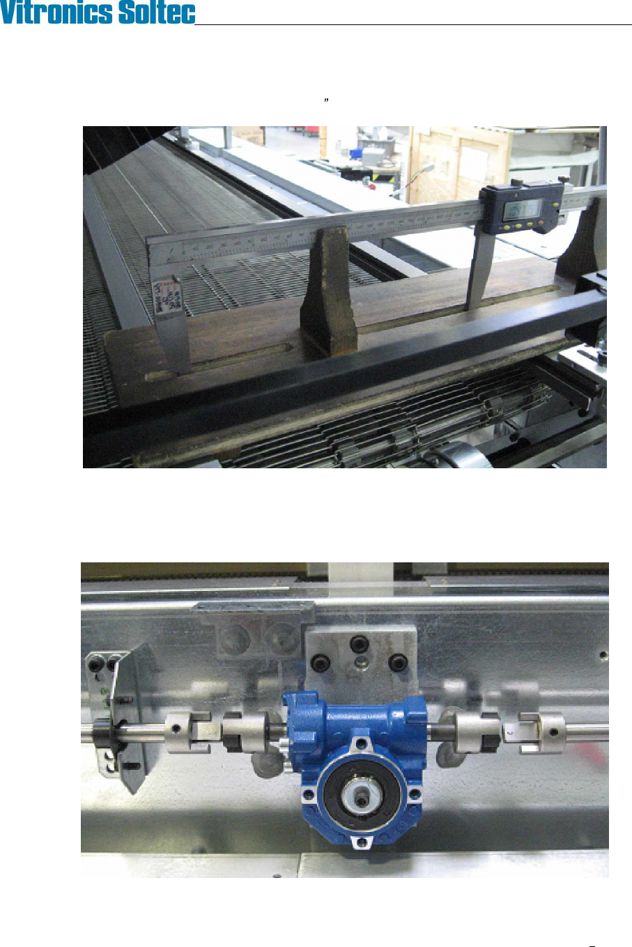
1. Measure lane width near the feedscrew locations: (onload, offload, and intermediates). The measured
width at all feed screws must fall within a .020 (0.5mm) range.
Digital calipers (in wooden support) measuring lane width at face above chain groove.
2. If adjustment is required de-couple the wormgear boxes from the width adjust shafts to allow turning one
feedscrew at a time. Adjust feedscrews by hand to bring the lane width variation into specification then
reconnect the width adjust shafts.
Decouple worm gear box and turn by hand to adjust parallel