XPM2_XPM3 Technical Ref Manual Conveyor1.pdf - 第31页
VI TRO NICS-SOLTEC REFLO W SOLDERING SYSTEMS Oc tober 10, 2008 31 XPM 2 / XPM 3 Technical Reference M anual C onv ey or Sy stem s SET XCS HEIGHT The he ight of the X CS sup port is adjus ted relativ e to the edg e rails …
VITRONICS-SOLTEC REFLOW SOLDERING SYSTEMS
October 10, 2008
30
XPM2 / XPM3 Technical Reference Manual Conveyor Systems
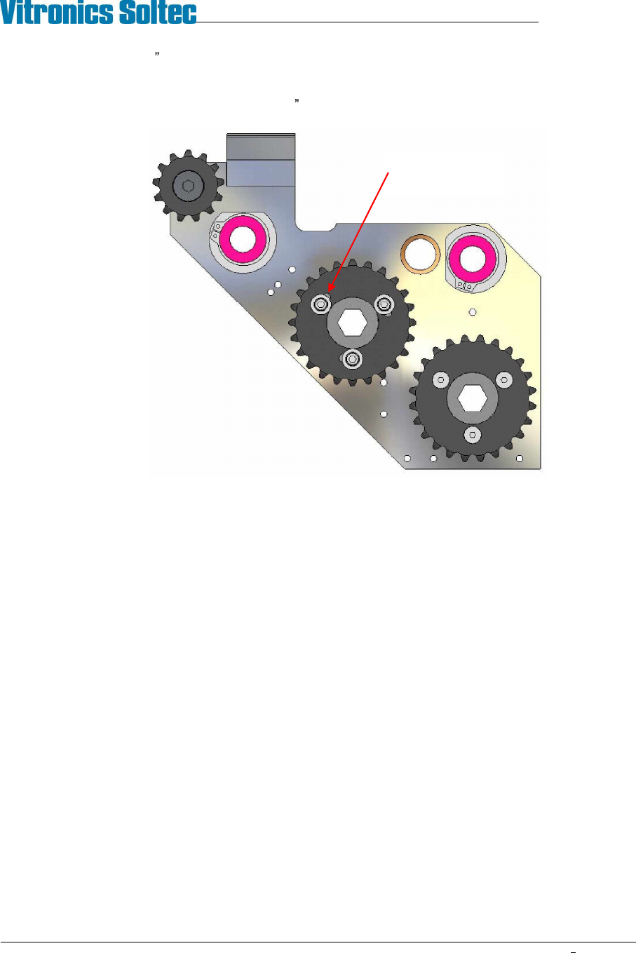
3. Make coarse (3/8 ) timing adjustments by moving the XCS chain ahead or back one tooth at a time on the
drive sprocket at the offload end of the machine.
4. Fine adjust the timing (within the last 3/8 ) by indexing the slotted drive sprocket on its hub.
5. Operate the conveyor and watch the interaction of the XCS plates and fixed rail pins through several
revolutions of the chain loops before moving the XCS into park position.
Indexable XCS
drive sprocket
VITRONICS-SOLTEC REFLOW SOLDERING SYSTEMS
October 10, 2008
31
XPM2 / XPM3 Technical Reference Manual Conveyor Systems
SET XCS HEIGHT
The height of the XCS support is adjusted relative to the edge rails by changing the thickness of the stainless steel
shims under the XCS rail at the gantry and intermediate locations. The height can also be adjusted between the
front and rear of the tunnel by raising or lowering the edge rails in the rail clamps (see INSTALL RAILS). Verify
tunnel clearance whenever edge rails are raised.
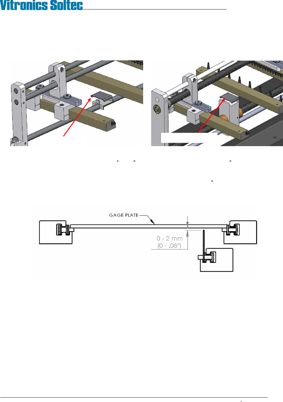
The height of the XCS is checked using an 18 or 22 wide aluminum gage plate and a .08 (2mm) feeler gauge:
1. Make sure the machine is leveled and properly resting on all feet.
2. Set the conveyor width for the gage plate and position the XCS rail about 1 (25mm) from the park
position.
3. Place the gage plate on the edge rail chains as you would a PCB.
4. Look below the plate and wiggle it to verify that the XCS fingers are not touching (too high). Move the
plate down the conveyor and repeat the check every couple of feet (½ meter) along the conveyor.
5. Next, move the gage plate to the first gantry. Verify that a 2mm feeler gauge will not pass between the
bottom of the plate and the XCS fingers. Check several XCS fingers in a row at each location. Move the
plate down the conveyor and repeat the check every couple of feet (½ meter) until you reach the last
gantry. The minimum XCS height does not apply between either end of the machine and the first support
location.
6. Move the position of the XCS rail to one inch from the moveable rail and repeat the test.
7. Move the XCS to the middle of the lane and repeat the test.
8. Change the thickness of the XCS shims and adjust edge rail height as necessary to bring all
measurements into specification. If edge rails are raised verify tunnel height. If XCS is lowered pass a
feeler gage or stiff paper under the length of the XCS rail to verify that it does not contact any ICBs.
Shim at gantry
Shim at intermediate
VITRONICS-SOLTEC REFLOW SOLDERING SYSTEMS
October 10, 2008
32
XPM2 / XPM3 Technical Reference Manual Conveyor Systems
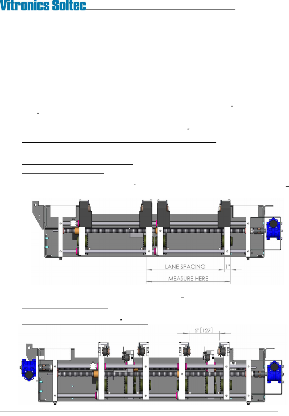
DUAL LANE DUAL XCS
The dual lane dual XCS conveyor system consists of two complete edge rail / XCS rail systems sharing a common
set of width adjust feed screws. Because the moveable components of the two lanes are coupled to the same
feedscrews the width and XCS position of the front and rear lanes remain identical.
DUAL LANE DUAL XCS LANE SPACING ADJUSTMENT
The distance between the two lanes is fixed at the factory. Adjustment of the lane spacing dimension is
accomplished by indexing (rotating) the acme nuts in the rail support plates of the front lane. The indexable nuts
are installed in the front lane rather then the rear lane to improve access to the adjusting mechanisms inside the
tunnel at the intermediate positions.
If starting with a conveyor that is not properly qualified, set the lane to lane spacing between the pair of rails on
each feed screw using the indexable Acme nuts (ref. steps 9 & 10 below), then refer to ALIGN AND PARALLEL
EDGE RAILS to set lane parallel.
If starting with a dual lane conveyor system that is properly set up and qualified, the most efficient method of
changing lane spacing is to move each rail an exact amount w/in ±.005 (±0.13mm) as follows:
1. Measure and record the distance from one fixed rail extrusion to the other at every attachment point
(onload, offload, gantry and intermediates). It does not matter what face of the rails is used for the
measurement as long as you are consistent.
2. Repeat step 1 for the moveable edge rails.
3. Repeat step 1 for the XCS rails.
4. Determine the current lane spacing: At the onload end measure the distance between the outside surfaces
of the two fixed rail end plates. Subtract 1 (25.4mm) from this measurement (example: 361.95mm
25.40mm = 336.55mm).
5. Calculate the amount all affected conveyor components need to move: Subtract the desired lane
spacing from the current lane spacing (example: 336.55mm 251mm = 85.55mm).
6. Establish the target lane settings: Subtract the amount to be moved from each of the width
measurements taken in steps 1 through 3.
7. Set the lane width at approximately 5 (125mm) using the conveyor width system.