XPM2_XPM3 Technical Ref Manual Conveyor1.pdf - 第21页
VI TRO NICS-SOLTEC REFLO W SOLDERING SYSTEMS Oc tober 10, 2008 21 XP M 2 / XPM 3 Technical Reference Manual Conv eyor Sy stem s SET LANE PARALLEL 1. Meas ure lane width near the f e eds crew locations : (onload, of f loa…
VITRONICS-SOLTEC REFLOW SOLDERING SYSTEMS
October 10, 2008
20
XPM2 / XPM3 Technical Reference Manual Conveyor Systems
ALIGN AND PARALLEL EDGE RAILS
ALIGN FIXED RAIL
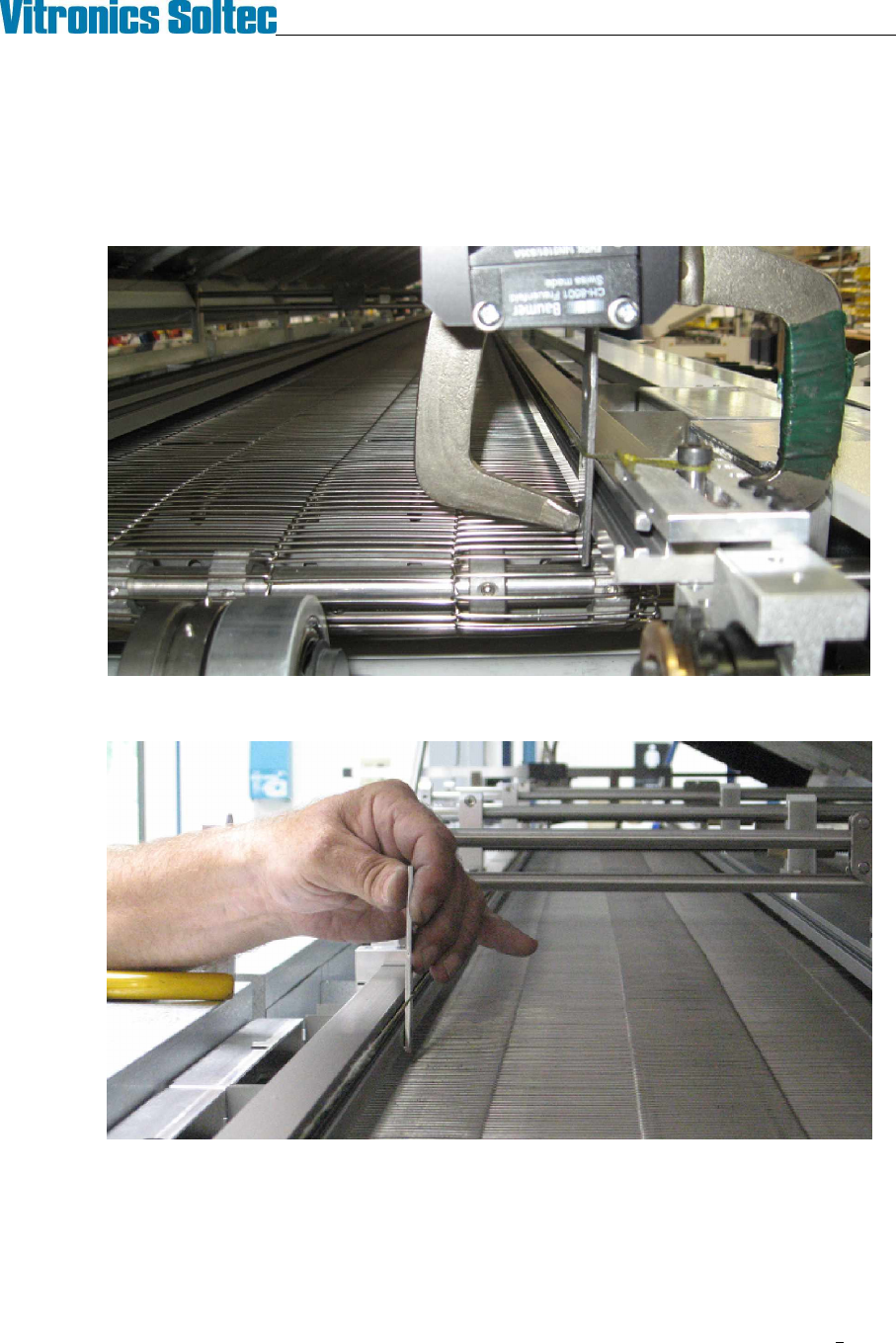
1. The fixed rail is adjusted straight using a string and three small metal plates of identical thickness.
2. Clamp one of the small plates to each end of the fixed rail and stretch a string between them.
3. Use the third plate to gauge the position of the rail at each gantry and intermediate.
4. Adjust the position of the intermediate and gantry fixed rail hangers on the cross bars to straighten the rail
relative to the string.
VITRONICS-SOLTEC REFLOW SOLDERING SYSTEMS
October 10, 2008
21
XPM2 / XPM3 Technical Reference Manual Conveyor Systems
SET LANE PARALLEL
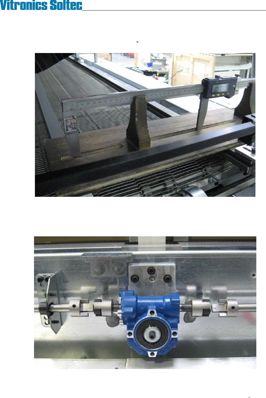
1. Measure lane width near the feedscrew locations: (onload, offload, and intermediates). The measured
width at all feed screws must fall within a .020 (0.5mm) range.
Digital calipers (in wooden support) measuring lane width at face above chain groove.
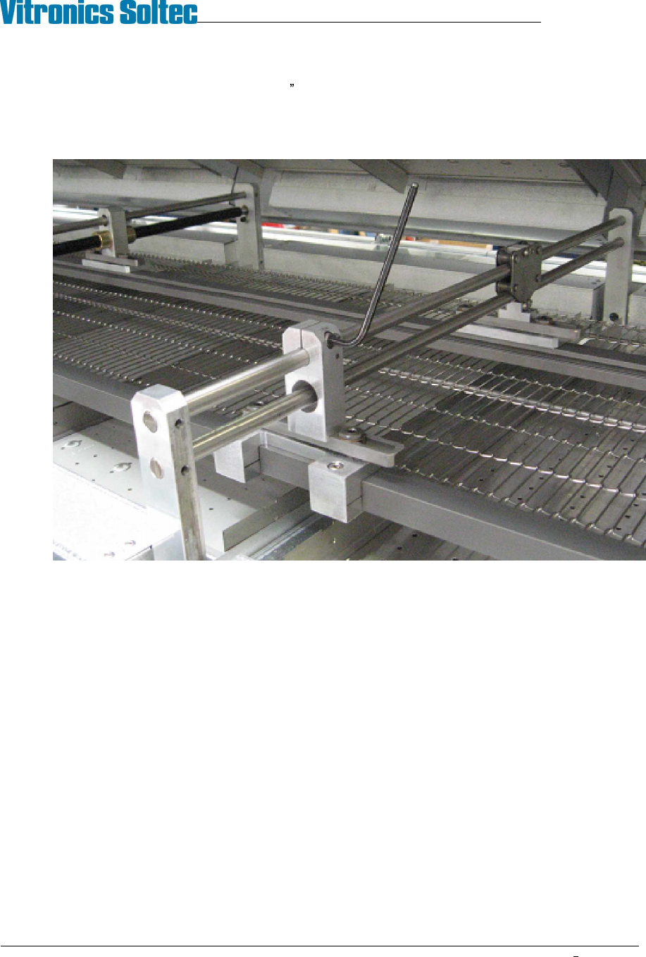
2. If adjustment is required de-couple the wormgear boxes from the width adjust shafts to allow turning one
feedscrew at a time. Adjust feedscrews by hand to bring the lane width variation into specification then
reconnect the width adjust shafts.
Decouple worm gear box and turn by hand to adjust parallel
VITRONICS-SOLTEC REFLOW SOLDERING SYSTEMS
October 10, 2008
22
XPM2 / XPM3 Technical Reference Manual Conveyor Systems
3. Measure lane width midway between the feedscrew locations. Compare measurements to width at the
feedscrews. Allowable variation is .052 (1.32mm).
4. If adjustment is required in the span between the feedscrews move the fixed rail hanger on the gantry to
bring the measurements into specification.