XPM2_XPM3 Technical Ref Manual Conveyor1.pdf - 第36页
VI TRO NICS-SOLTEC REFLO W SOLDERING SYSTEMS Oc tober 10, 2008 36 XPM 2 / XPM 3 Technical Reference M anual C onv ey or Sy stem s 15 . Reset the location of the end of t rav el lim it sw itch block so t ha t i t stops t …
VITRONICS-SOLTEC REFLOW SOLDERING SYSTEMS
October 10, 2008
35
XPM2 / XPM3 Technical Reference Manual Conveyor Systems
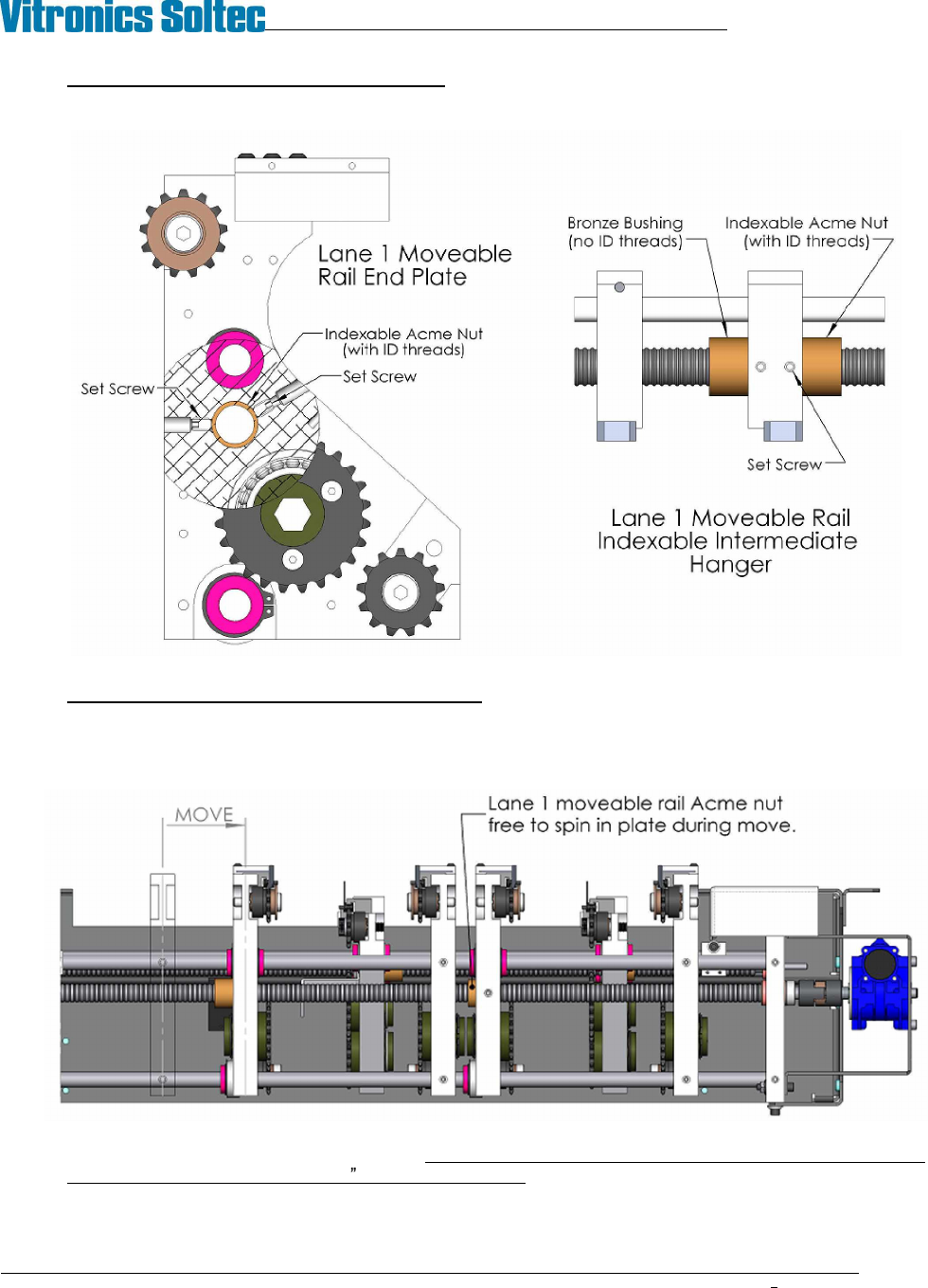
12. Decouple the lane 1 moveable rail Acme nuts: Loosen the set screws in the onload and offload end plates
and intermediate rail hanger(s). Note that there are two set screws acting on the Acme nut in each of the
end plates.
13. Move the lane 2 moveable rail toward the fixed rail by operating the edge rail width adjust system. Make
the move in small increments, stopping to rotate the indexable Acme nuts in lane 1 so that the rail stays
straight and does not run into the XCS. It may be necessary to temporarily remove the moveable rail and
chain from lane 1 while performing this step.
14. When the moveable rail is close to position adjust each of the lane 1 moveable rail Acme nuts to achieve
the exact target dimensions (±.005 ) calculated in step 6. Be very careful to not over tighten the set
screws when locking down the adjustable Acme nuts. It is very easy to distort the Acme threads and
cause the nut to bind on the feedscrew.
VITRONICS-SOLTEC REFLOW SOLDERING SYSTEMS
October 10, 2008
36
XPM2 / XPM3 Technical Reference Manual Conveyor Systems
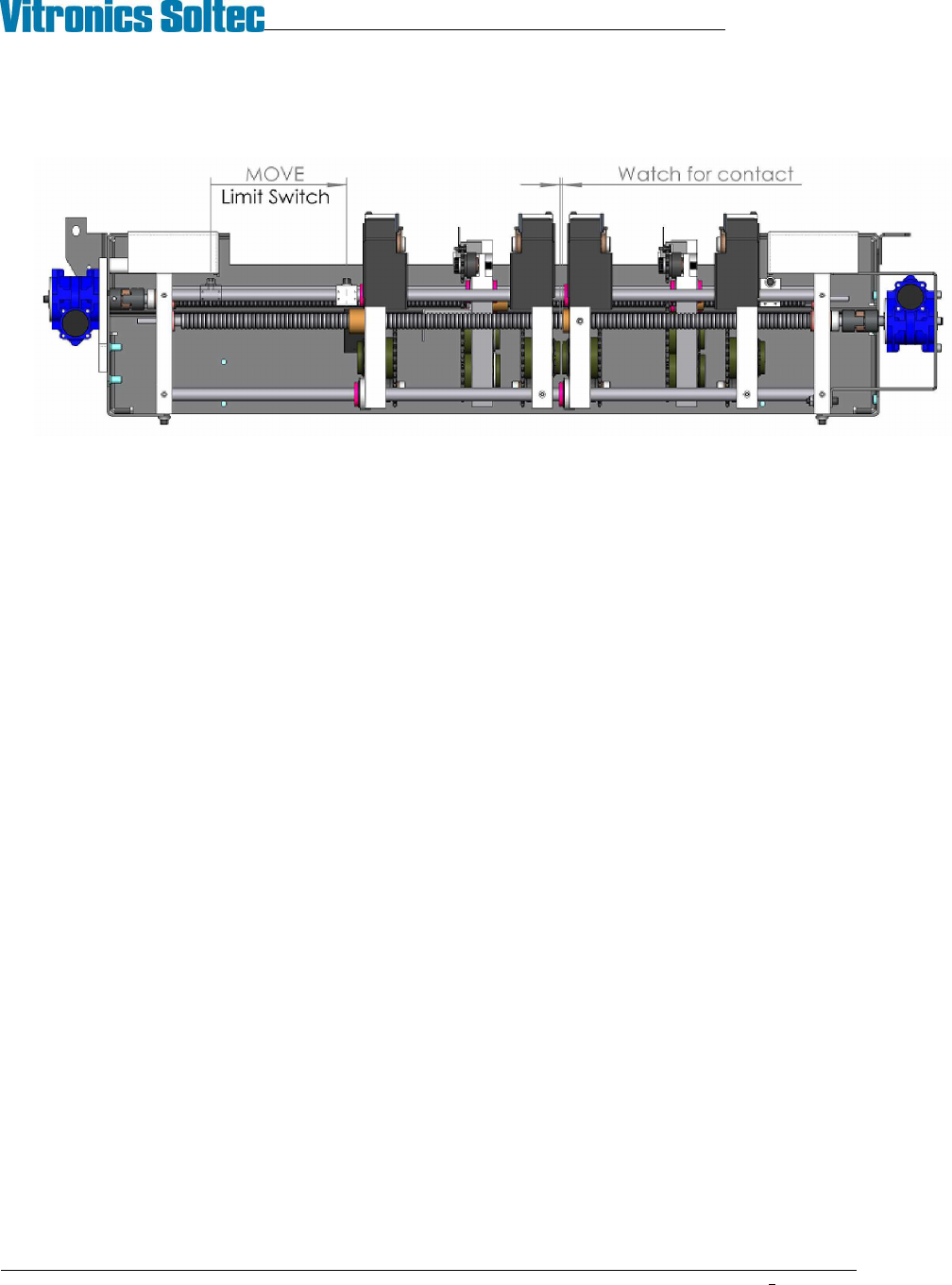
15. Reset the location of the end of travel limit switch block so that it stops the moveable rail before the lane 1
moveable end plate contacts the lane 2 fixed endplate.
16. Verify all lane parallel and XCS height measurements before returning machine to service.
VITRONICS-SOLTEC REFLOW SOLDERING SYSTEMS
October 10, 2008
37
XPM2 / XPM3 Technical Reference Manual Conveyor Systems
CONVEYOR DRIVE SYSTEM
The oven controller supplies an analog voltage reference signal between 0 and 10 volts to the conveyor motor
electronics to set the desired conveyor speed. The A42 board divides it in half and passes it through an Opamp to
avoid loading and signal loss issues from the resistor voltage divider before it sends it to pin 9 on the Integramotor.
The internal Integramotor electronics require a regulated power supply between 20 and 28 volts to operate,
otherwise the electronics indicate a fault condition and the motor will not operate. The internal Integramotor
electronics control the motor speed based on a 0- 5VDC reference signal that is supplied by dividing the 0-10VDC
analog output voltage in half.
The speed of a brushless motor is not controlled by varying the voltage to the windings of the motor like a brush
type or a universal motor is controlled. The speed and rotation direction of a brushless motor is controlled in a
similar method to that of a stepper motor. Through switching the motor windings on and off in a specific sequence
for a specific direction. The faster the windings are switched on and off using the specified sequence the faster the
motor rotates.
One major difference with a brushless motor versus a stepper motor is that a brushless motor has built in hall-
effect sensors that are used by the drive electronics to sense and to regulate how fast the motor is rotating. A
stepper motor has no internal feedback and no speed regulation.
The internal Integramotor electronics switch the windings of the motor faster as the 0-5VDC reference signal is
increased while regulating the speed of the motor through the feedback from the built in hall-effect sensors.
A hall-effect sensor built into the conveyor motor supplies pulses to the oven controller, which is used by the
controller for feedback to close loop the conveyor speed to the setpoint by varying the analog voltage signal to the
conveyor motor electronics.
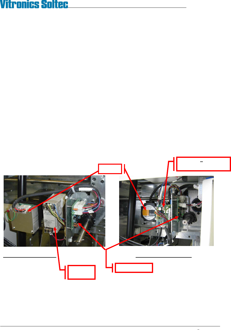
Integra Motor assembly Oriental Motor Assembly
Set up the Conveyor Drive within the Oven Operation Program.
NOTE: This operation may require a password.
G5 Power
supply
A42 Board
Motor
V1 Board Oriental
motor only