XPM2_XPM3 Technical Ref Manual Conveyor1.pdf - 第12页
VI TRO NICS-SOLTEC REFLO W SOLDERING SYSTEMS Oc tober 10, 2008 12 XP M 2 / XPM 3 Technical Reference Manual Conv eyor Sy stem s 4. Start with the splice cli p at one edge of the belt. Using a s crewdriver or needle nos e…
VITRONICS-SOLTEC REFLOW SOLDERING SYSTEMS
October 10, 2008
11
XPM2 / XPM3 Technical Reference Manual Conveyor Systems
CONVEYOR BELT, CHAIN & RAIL SERVICE
REMOVE AND REPLACE CONVEYOR MESH BELT
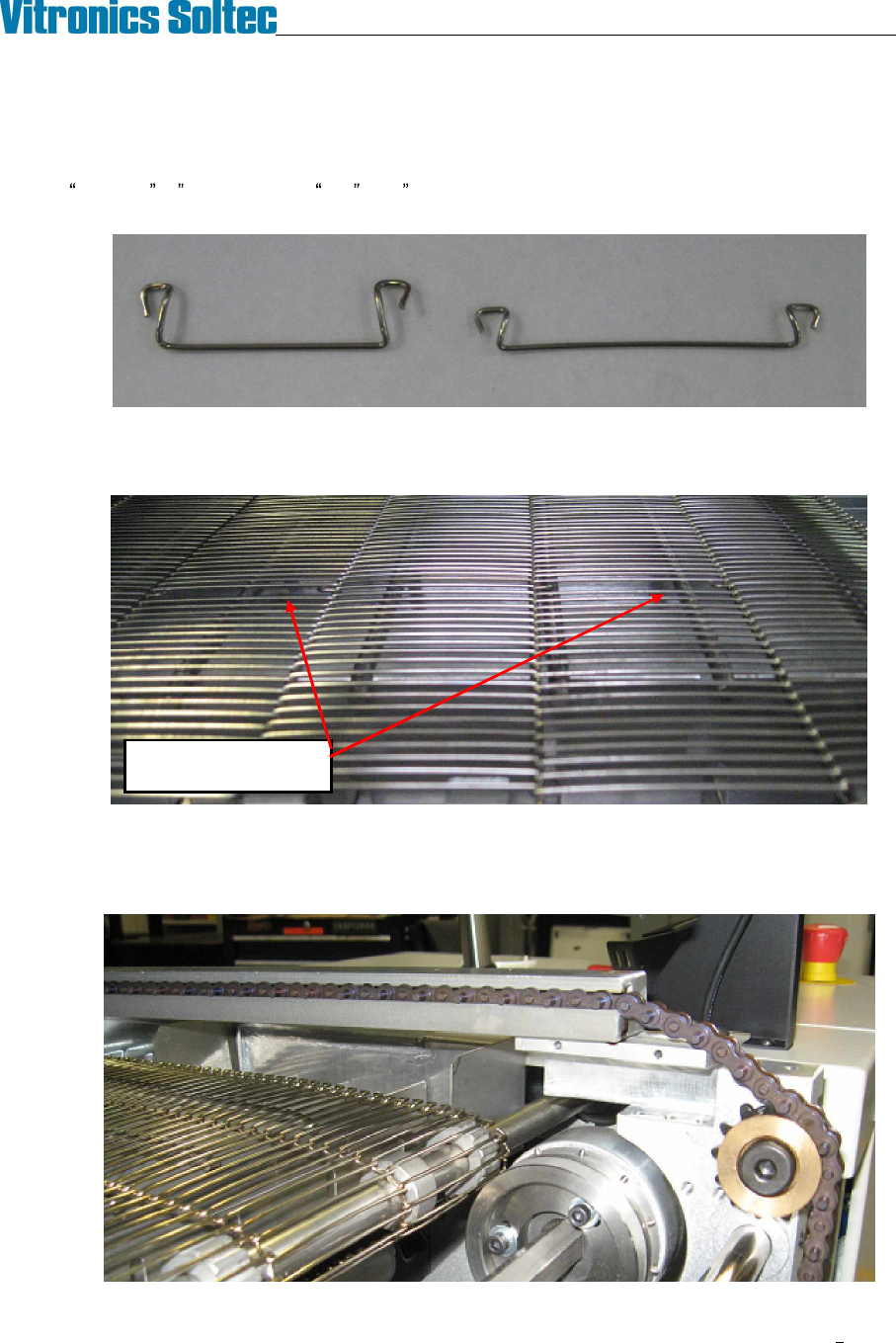
1. The mesh belts installed on XPM2 and XPM3 are available in several widths and in two different pitches,
standard ½ (12.7mm) and fine .286 (7.26mm). If splice clips are to be replaced verify that you have
the correct clips for the specific mesh belt.
2. Locate the splice point in the mesh belt by finding the double size 'holes' created by the splice clips. There
are four to six splice clips, depending on the width of the belt. For ease of access, turn the conveyor until
the splice point is positioned just inside the oven over one of the deck pans.
3. On conveyor systems with edge rails remove the chain guards from the rail ends near the splice clips,
remove the shoulder bolts that retain the rails in the capture brackets, and reposition the rails on top of the
capture brackets. It is not necessary to break the edge rail chains. Raising the rails will greatly improve
the working space above the mesh belt splice clips.
Double size holes at
Mesh Belt Splice Clips
VITRONICS-SOLTEC REFLOW SOLDERING SYSTEMS
October 10, 2008
12
XPM2 / XPM3 Technical Reference Manual Conveyor Systems
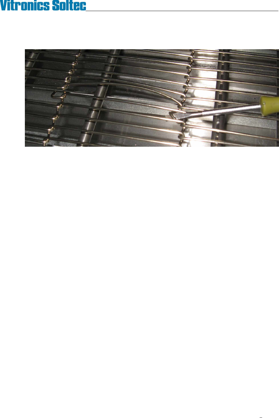
4. Start with the splice clip at one edge of the belt. Using a screwdriver or needle nose pliers unhook one
side of the clip from the belt. Rotate the clip through the belt to unhook its other end and remove it from
the belt.
5. Remove the remaining clips in the same manner to separate the mesh belt.
6. Installation is the reverse of removal. It may be helpful to temporarily bind the ends of the mesh belt
together with tie-wraps while installing the splice clips.
VITRONICS-SOLTEC REFLOW SOLDERING SYSTEMS
October 10, 2008
13
XPM2 / XPM3 Technical Reference Manual Conveyor Systems
REMOVE AND REPLACE EDGE RAIL CONVEYOR CHAINS AND RAILS
REMOVE CHAINS
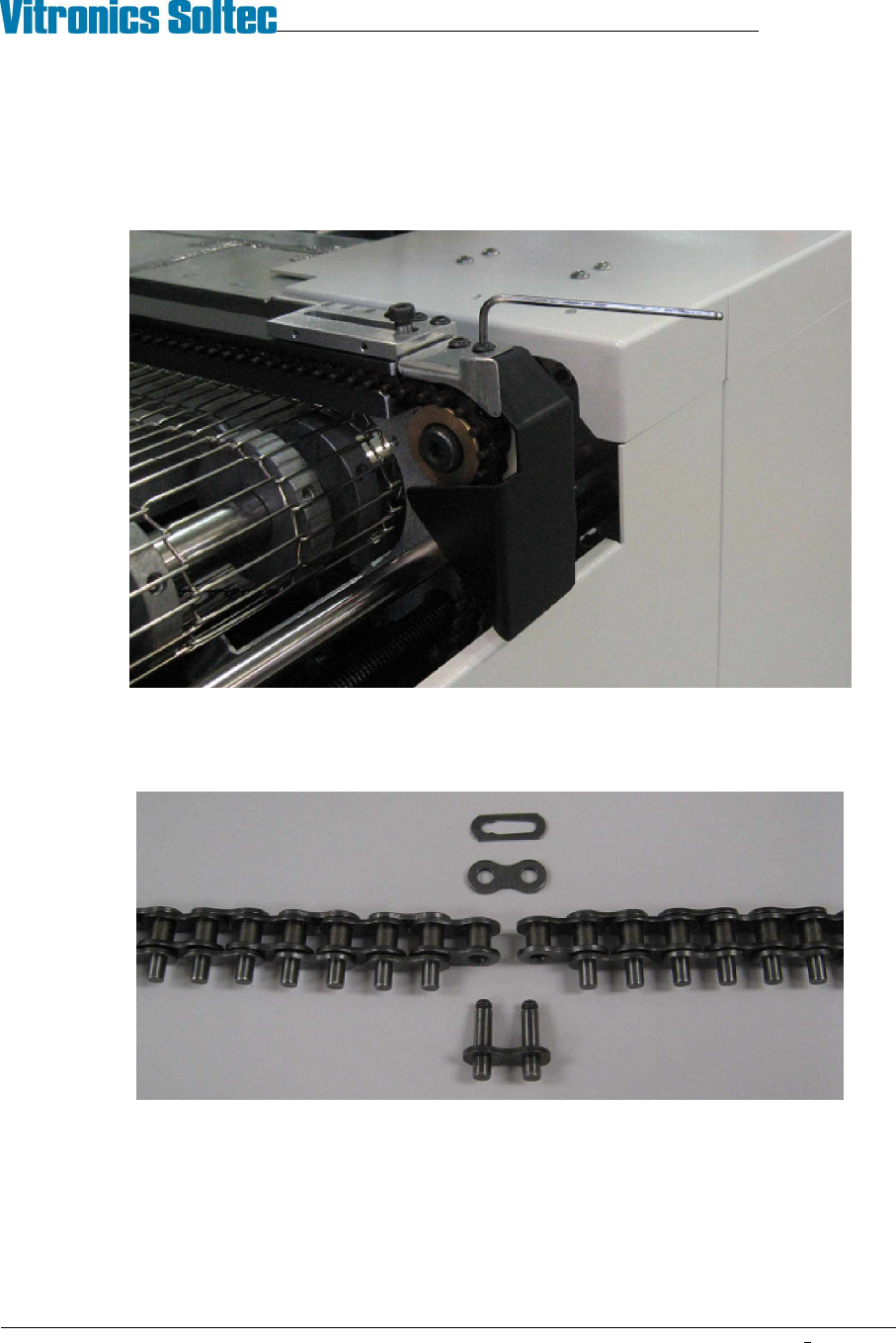
1. At the off-load end of the oven, remove the chain guard from each rail by removing the button head
screws with a 1/8" hex key.
2. Run the conveyor until the master link for one of the chains comes up just under the rail. Remove the
master link from the chain and unthread the chain from all of the sprockets that it wraps around on its
way under the oven. Make sure that the chain is off the drive sprocket and tie-wrap it to the idler shaft
just below the end of the oven.
3. Go to the on-load end of the oven and remove the chain guards. Pull the chain out of the rail and let it
drop down. Tie wrap the end of the chain to the idler shaft below the end of the oven.
4. Repeat steps 2. and 3. to remove the chain from the remaining edge rail(s).