XPM2_XPM3 Technical Ref Manual Conveyor1.pdf - 第45页
VI TRO NICS-SOLTEC REFLO W SOLDERING SYSTEMS Oc tober 10, 2008 45 XPM 2 / XPM 3 Technical Reference M anual C onv ey or Sy stem s COMPUTER CONTROLL ED AUTO RA IL ADJU ST Auto Ra il Ad jus t i s: ! Standa rd, (install ed …
VITRONICS-SOLTEC REFLOW SOLDERING SYSTEMS
October 10, 2008
44
XPM2 / XPM3 Technical Reference Manual Conveyor Systems
Verify that each of the 2 manual rail in/out switch status indicator leds changes state on the rail controller
(A42) when the manual rail in/out switch is actuated in each direction. Each manual switch led status
indicator lights when the manual rail in/out switch is held on one direction.
If the rail in/out selections do not cause the corresponding status indicators to change on the rail controller
board to change, there MAY be a wiring error with the rail selector switch.
Verify that the jumpers are installed correctly on connector P62 on the A1 board. Also verify that there is
~130 VDC at connector P62 on the A1 board between pins 1 and 4.
Enable the manual rail switch.
Select Rail IN : A1-K24 or A1-K26 should energize depending on which rail is selected for movement.
A1-K22 should energize after a delay.
Select Rail OUT :A1-K23 or A1-K25 should energize depending on which rail is selected for movement.
A1-K22 should energize after a delay.
After the rail selection logic has been corrected, check to see that the wiring to the motor is correct.
Disable the manual rail adjust.
Enable the manual rail adjust.
Check the operation of both the in and the out adjust switch positions.
Disable the manual rail adjust.

VITRONICS-SOLTEC REFLOW SOLDERING SYSTEMS
October 10, 2008
45
XPM2 / XPM3 Technical Reference Manual Conveyor Systems
COMPUTER CONTROLLED AUTO RAIL ADJUST
Auto Rail Adjust is:
! Standard, (installed on all ovens) ) An option, (NOT installed on all ovens)
DESCRIPTION
The Oven Control Program automatically adjusts the rail in/out to meet the board size entered in the PRODUCT
file in the Oven Control Program.
OPERATION
Run the Automatic rail adjust within the Oven Operation Program. NOTE: This operation may require a
password.
(The direction of travel of the rail and the speed of the width adjust may be selected by choices in the Oven
Operation Program.)
While conducting the following tests ensure that each rail moves to its minimum or maximum value and stop. The
rail adjust system is designed to stop at these positions.
1. Verify that the DC drive card is receiving 120 VAC power between terminals L1 and L2. If not, verify that K37
is energized.
2. Check that the I/O board relay A1-K22 is energized.
3. Measure and verify that the voltage at wire number V2+ at P45 pin 1 on the I/O board is +10 VDC.
4. If voltage is present, check the wiring at the signal input of the DC Drive.
5. If the preceding steps check out, measure the DC voltage output of the DC drive circuit board between
terminals A1 and A2. Voltage present should be 90-130 VDC. If there is no voltage present, the drive circuit
board is likely to be defective. Otherwise, adjust the SIGNAL ADJUST potentiometer on the DC drive board to
produce the 90-130 VDC.
If steps 1-5 have been performed and the rail motor still does not operate, refer to the Oven Schematics and
proceed with the following:
1. Verify the status of the rail limit switches by observing the status leds on the A40 board. These right angle
leds on the outer edge of the A40 board. A rail is not allowed to move if the corresponding limit switch led
on the A40 board is off in the desired direction to move. The A40 board will not energize relay A1-K22 if a
rail is not allowed to move due to a limit switch input not being present. This also applies for all of the
direction control relays A1-K23 through A1-K26.
2. Verify that the rail enable relay A1-K22 is energized.
3. Verify that the rail out relay A1-K23 or A1-K25 for the corresponding rail axis to move is energized.
4. If the correct relays are energized, check the associated wiring.
5. If the rail motor still does not turn, press an e-stop switch to disable 120 VAC control power.
6. Using an Ohm meter, verify that there is continuity through each rail limit switch.
(If either the switch is wired incorrectly or the rail is pressed up against the limit switch,
there should be no
continuity through the switch.)
7. Pull out the E-stop recently pressed and reset the E-Stop in the Oven Control Program.
VITRONICS-SOLTEC REFLOW SOLDERING SYSTEMS
October 10, 2008
46
XPM2 / XPM3 Technical Reference Manual Conveyor Systems
After the rail out function has been tested, the rail in function check out should be greatly reduced. Activate the
rail in function in the Oven Operation Program (this is assuming you have already logged into the software as
previously described). The part of the auto rail circuit which can be a problem is the rail in limit switch. The test
procedure for these components would be the same as described for the rail out circuit.
Rail Position Encoder
The final check out procedure is to verify that the rail position encoder feedback signal is being received and
processed by the computer.
A rotary quadrature encoder has a minimum of 2 sets of lines on a circular shaped disk instead of only one set on
a single ended encoder. One set of lines is 90 degrees out of phase with the other to allow the rotation direction of
a shaft to be determined. There is an optical decoder and output signal for each set of lines designated as output
channel A and output channel B. The rotation direction of a quadrature encoder is determined by monitoring which
output channel signal is ahead of or leading the other.
The rail width adjust on the XPM3 uses a 250 pulse per revolution quadrature encoder mounted on the end of a
lead screw. The lead screw is a ¾-10 acme screw, which translates to 10 turns to move a rail one-inch or 2.54 cm
of travel.
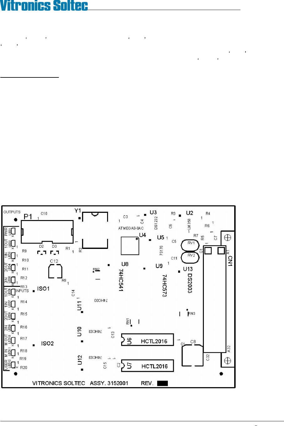
The two axis rail controller board 3152001 utilizes a quadrature counter for the auto rail option. On the 3152001
two axis controller a quadrature counter IC must be installed by inserting a HCTL-2016 device into a separate 16
pin DIP socket for each of the 2 possible auto rail axes to be controlled. U6 is the quadrature counter location for
the first axis and U7 is the quadrature counter location for the second axis. On the next generation 3152010 two
axis controller two quadrature counters are part of the base board through a single surface mount device. This was
due to the HCTL-2016 being obsoleted and discontinued by the manufacturer Agilent technologies.
3152001A Existing two axis rail control board.
U6 and U7 are only installed for auto rail options.