XPM2_XPM3 Technical Ref Manual Conveyor1.pdf - 第26页
VI TRO NICS-SOLTEC REFLO W SOLDERING SYSTEMS Oc tober 10, 2008 26 XPM 2 / XPM 3 Technical Reference M anual C onv ey or Sy stem s ALIGN XCS RAIL 1. Verif y that the edge rail sys te m is aligned an d adjusted pa ra llel …
VITRONICS-SOLTEC REFLOW SOLDERING SYSTEMS
October 10, 2008
25
XPM2 / XPM3 Technical Reference Manual Conveyor Systems
3. Slide the XCS rail out of the other capture bracket and carefully remove it from the machine.
!!! Exercise extreme care when handling the XCS rail.
DO NOT let the rail bend or it may be permanently deformed.
Watch for height adjustment shims that may be installed at the gantry and intermediate positions.
Keep the shims away from the cell ducts. Do not swap these shims between locations.
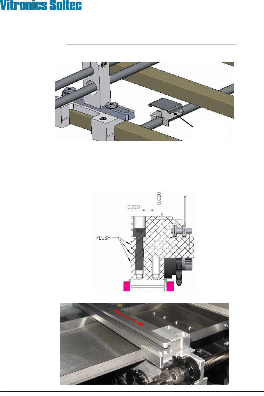
INSTALL XCS RAIL
1. Visually inspect the rail for straightness and wear or damage to the chain guide surface.
2. Carefully place the rail in the XCS support nests
3. Install the XCS rail capture brackets on each end of the machine. Position the rear face of the capture
brackets flush with the rail end plates. Use care to not pinch the XCS rail with the capture brackets.
4. Slide the XCS rail back and forth in the rail capture brackets to test that there is no binding.
XCS height
adjust shim
VITRONICS-SOLTEC REFLOW SOLDERING SYSTEMS
October 10, 2008
26
XPM2 / XPM3 Technical Reference Manual Conveyor Systems
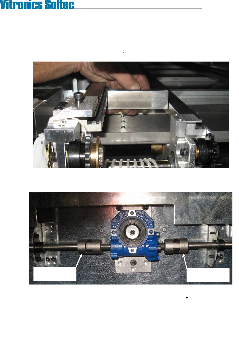
ALIGN XCS RAIL
1. Verify that the edge rail system is aligned and adjusted parallel within specification.
2. Use a gauge block and feeler gauges or a pair of calipers to measure the distance from the fixed edge rail
to the XCS rail near each of the feedscrew locations: (onload, offload, and intermediates). The measured
width at all feed screws must fall within a .020 (0.5mm) range.
3. If adjustment is required de-couple the wormgear boxes at the rear of the machine from the width adjust
shafts to allow turning one feedscrew at a time. Adjust feedscrews by hand to bring the XCS rail location
into specification then reconnect the width adjust shafts.
4. Verify XCS parallel in the spans between the feedscrew locations. The distance from the fixed edge rail to
the XCS rail midway between the feedscrew locations must be within .052 (1.32mm) of the measurement
at the feedscrews. XCS parallel can not be adjusted at the gantry locations. Replace the XCS rail if
variation is excessive.
Loosen set screw
and slide hub
right
Loosen set screw
and slide hub left
VITRONICS-SOLTEC REFLOW SOLDERING SYSTEMS
October 10, 2008
27
XPM2 / XPM3 Technical Reference Manual Conveyor Systems
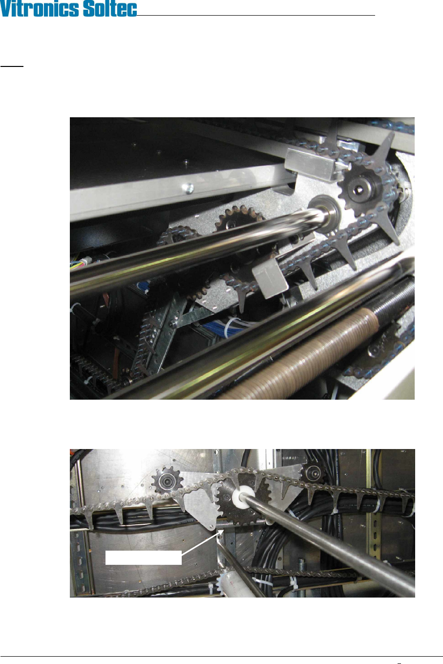
INSTALL XCS CHAIN
Note: The XCS chain is custom manufactured as a pitch matched set with the fixed edge rail chain. Do not mix or
splice these chains. Always replace both chains as a set.
1. Feed the XCS chain into the offload end of the XCS rail until it reaches the opposite end of the machine.
2. Continue to thread the XCS chain over the sprockets at the on-load end then feed it back under the oven.
XCS chain routing typical, both ends
3. Thread the XCS chain through the tensioner trolley at the center of the return loop. The XCS tensioner
trolley is properly oriented when its extension spring is beneath the large sprocket.
Spring side down