XPM2_XPM3 Technical Ref Manual Conveyor1.pdf - 第44页
VI TRO NICS-SOLTEC REFLO W SOLDERING SYSTEMS Oc tober 10, 2008 44 XPM 2 / XPM 3 Technical Reference M anual C onv ey or Sy stem s Verif y that each of the 2 manual rail in/out sw it ch s tatus indicator leds chang es s…
VITRONICS-SOLTEC REFLOW SOLDERING SYSTEMS
October 10, 2008
43
XPM2 / XPM3 Technical Reference Manual Conveyor Systems
RAIL WIDTH ADJUST
OPERATION:
Run the Manual rail adjust within the Oven Control Program. NOTE: This operation may require a password.
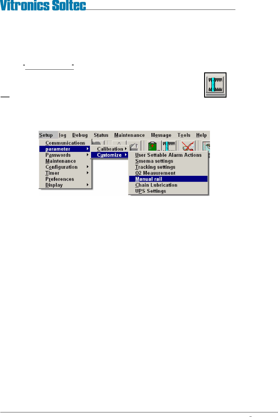
Manual rail adjust can be activated by clicking on the rail width adjust icon,
OR
by selecting Setup, Parameter, Customize, Manual Rail from the menu bar.
Test Procedure
1. Enable the manual rail adjust.
2. Select the rail to move if the oven has more then one rail adjust axis installed. The manual in/out rail switch is
a momentary 3 position rotary switch with a spring return to the center position and the center position is the
off position. None of the rails will move until the manual in/out switch is rotated and held in one direction.
The rail controller (A42) is a stand-alone controller that executes commands sent by the DI board through
RS485 communication. The rail controller (A42) only activates one of the rail direction relays (A1-K23 through
A1-K26) if the corresponding limit switch input is on or present. The rail controller (A42) activates the enable
output relay A1-K22 one second after one of the rail direction relays (A1-K23 through A1-K26) has been set.
3. Turn the rail in/out button in one direction. If the rail motor does not turn, turn the button in the other direction.
If the motor still does not turn, refer to the Oven Schematics and perform the following test procedure:
Disable the manual rail adjust.
Verify that the run status led on the rail controller (A42) is flashing. If the led is not flashing then there is a
problem with the rail controller board (A42).
Verify that the rail controller (A42) is firmly seated into the A1 board. If the run status led is not flashing
then the rail controller (A42) needs to be replaced.
If the run status led is flashing then verify that the cable from connector P3 on the front of the DI board to
connector P48 on the A1 board is installed correctly and that there are no loose wires on either connector.
Verify that the COM3 RXD and COM3 TXD leds on the front of the DI board flash periodically to indicate
that there is RS485 communication activity from the DI board to the rail controller (A42) and other boards
connected to the RS485 network.
The rail controller (A42) will not activate any of the rail output relays without RS485 communications being
initiated from the DI board.
Verify that the rail limit switch input status indicators are on on the rail controller (A42).
VITRONICS-SOLTEC REFLOW SOLDERING SYSTEMS
October 10, 2008
44
XPM2 / XPM3 Technical Reference Manual Conveyor Systems
Verify that each of the 2 manual rail in/out switch status indicator leds changes state on the rail controller
(A42) when the manual rail in/out switch is actuated in each direction. Each manual switch led status
indicator lights when the manual rail in/out switch is held on one direction.
If the rail in/out selections do not cause the corresponding status indicators to change on the rail controller
board to change, there MAY be a wiring error with the rail selector switch.
Verify that the jumpers are installed correctly on connector P62 on the A1 board. Also verify that there is
~130 VDC at connector P62 on the A1 board between pins 1 and 4.
Enable the manual rail switch.
Select Rail IN : A1-K24 or A1-K26 should energize depending on which rail is selected for movement.
A1-K22 should energize after a delay.
Select Rail OUT :A1-K23 or A1-K25 should energize depending on which rail is selected for movement.
A1-K22 should energize after a delay.
After the rail selection logic has been corrected, check to see that the wiring to the motor is correct.
Disable the manual rail adjust.
Enable the manual rail adjust.
Check the operation of both the in and the out adjust switch positions.
Disable the manual rail adjust.
VITRONICS-SOLTEC REFLOW SOLDERING SYSTEMS
October 10, 2008
45
XPM2 / XPM3 Technical Reference Manual Conveyor Systems
COMPUTER CONTROLLED AUTO RAIL ADJUST
Auto Rail Adjust is:
! Standard, (installed on all ovens) ) An option, (NOT installed on all ovens)
DESCRIPTION
The Oven Control Program automatically adjusts the rail in/out to meet the board size entered in the PRODUCT
file in the Oven Control Program.
OPERATION
Run the Automatic rail adjust within the Oven Operation Program. NOTE: This operation may require a
password.
(The direction of travel of the rail and the speed of the width adjust may be selected by choices in the Oven
Operation Program.)
While conducting the following tests ensure that each rail moves to its minimum or maximum value and stop. The
rail adjust system is designed to stop at these positions.
1. Verify that the DC drive card is receiving 120 VAC power between terminals L1 and L2. If not, verify that K37
is energized.
2. Check that the I/O board relay A1-K22 is energized.
3. Measure and verify that the voltage at wire number V2+ at P45 pin 1 on the I/O board is +10 VDC.
4. If voltage is present, check the wiring at the signal input of the DC Drive.
5. If the preceding steps check out, measure the DC voltage output of the DC drive circuit board between
terminals A1 and A2. Voltage present should be 90-130 VDC. If there is no voltage present, the drive circuit
board is likely to be defective. Otherwise, adjust the SIGNAL ADJUST potentiometer on the DC drive board to
produce the 90-130 VDC.
If steps 1-5 have been performed and the rail motor still does not operate, refer to the Oven Schematics and
proceed with the following:
1. Verify the status of the rail limit switches by observing the status leds on the A40 board. These right angle
leds on the outer edge of the A40 board. A rail is not allowed to move if the corresponding limit switch led
on the A40 board is off in the desired direction to move. The A40 board will not energize relay A1-K22 if a
rail is not allowed to move due to a limit switch input not being present. This also applies for all of the
direction control relays A1-K23 through A1-K26.
2. Verify that the rail enable relay A1-K22 is energized.
3. Verify that the rail out relay A1-K23 or A1-K25 for the corresponding rail axis to move is energized.
4. If the correct relays are energized, check the associated wiring.
5. If the rail motor still does not turn, press an e-stop switch to disable 120 VAC control power.
6. Using an Ohm meter, verify that there is continuity through each rail limit switch.
(If either the switch is wired incorrectly or the rail is pressed up against the limit switch,
there should be no
continuity through the switch.)
7. Pull out the E-stop recently pressed and reset the E-Stop in the Oven Control Program.