XPM2_XPM3 Technical Ref Manual Conveyor1.pdf - 第47页
VI TRO NICS-SOLTEC REFLO W SOLDERING SYSTEMS Oc tober 10, 2008 47 XPM 2 / XPM 3 Technical Reference M anual C onv ey or Sy stem s 315 201 0A f uture two axis controller board. Each q uadrat ure cou nter has a digital inp…
VITRONICS-SOLTEC REFLOW SOLDERING SYSTEMS
October 10, 2008
46
XPM2 / XPM3 Technical Reference Manual Conveyor Systems
After the rail out function has been tested, the rail in function check out should be greatly reduced. Activate the
rail in function in the Oven Operation Program (this is assuming you have already logged into the software as
previously described). The part of the auto rail circuit which can be a problem is the rail in limit switch. The test
procedure for these components would be the same as described for the rail out circuit.
Rail Position Encoder
The final check out procedure is to verify that the rail position encoder feedback signal is being received and
processed by the computer.
A rotary quadrature encoder has a minimum of 2 sets of lines on a circular shaped disk instead of only one set on
a single ended encoder. One set of lines is 90 degrees out of phase with the other to allow the rotation direction of
a shaft to be determined. There is an optical decoder and output signal for each set of lines designated as output
channel A and output channel B. The rotation direction of a quadrature encoder is determined by monitoring which
output channel signal is ahead of or leading the other.
The rail width adjust on the XPM3 uses a 250 pulse per revolution quadrature encoder mounted on the end of a
lead screw. The lead screw is a ¾-10 acme screw, which translates to 10 turns to move a rail one-inch or 2.54 cm
of travel.
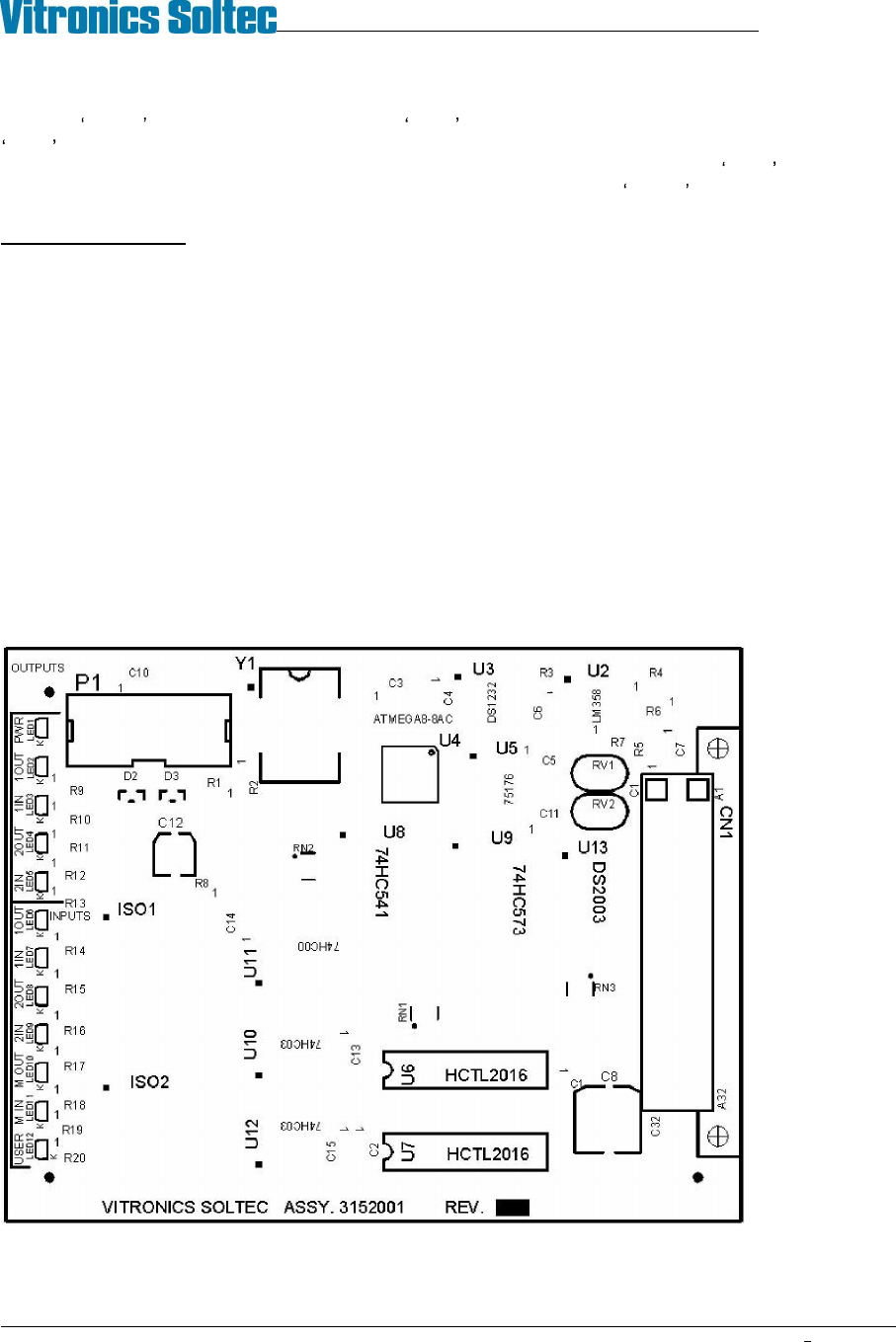
The two axis rail controller board 3152001 utilizes a quadrature counter for the auto rail option. On the 3152001
two axis controller a quadrature counter IC must be installed by inserting a HCTL-2016 device into a separate 16
pin DIP socket for each of the 2 possible auto rail axes to be controlled. U6 is the quadrature counter location for
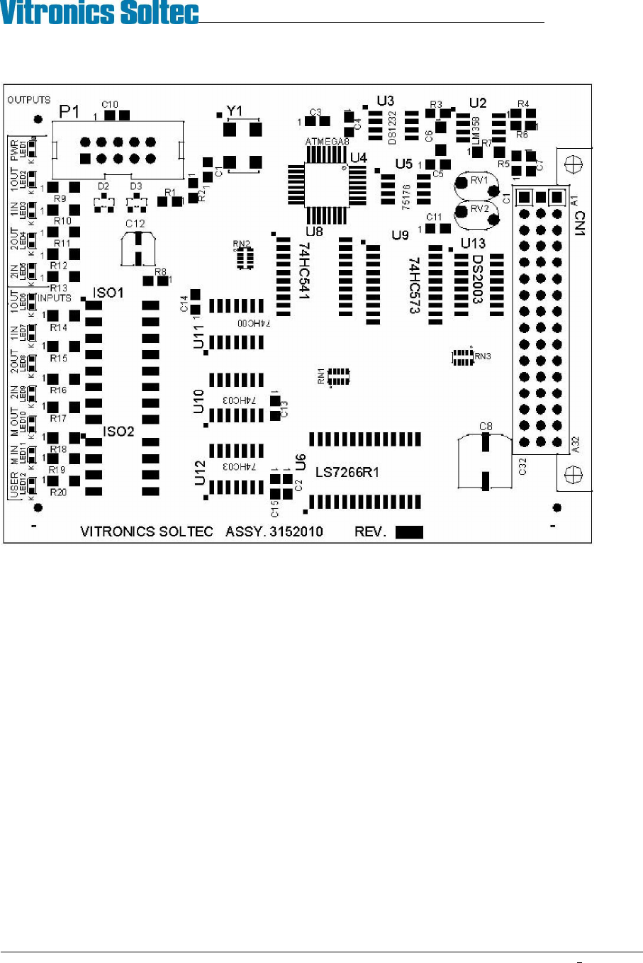
the first axis and U7 is the quadrature counter location for the second axis. On the next generation 3152010 two
axis controller two quadrature counters are part of the base board through a single surface mount device. This was
due to the HCTL-2016 being obsoleted and discontinued by the manufacturer Agilent technologies.
3152001A Existing two axis rail control board.
U6 and U7 are only installed for auto rail options.
VITRONICS-SOLTEC REFLOW SOLDERING SYSTEMS
October 10, 2008
47
XPM2 / XPM3 Technical Reference Manual Conveyor Systems
3152010A future two axis controller board.
Each quadrature counter has a digital input filter that is synchronized with the 8 megahertz microcontroller clock on
the two axis rail controller board to filter out noise on the channel A and channel B inputs for each quadrature
encoder.
Each quadrature counter is set up to count on every state transition (count up and count down) from a quadrature
encoder. This is called 4X mode and results in the 250 pulse per revolution encoder used on the rail width adjust
producing an equivalent of 1000 counts per revolution instead of 250.
The quadrature counter used on the two axis rail controller is a 16 bit counter on the 3152001 board and a 24 bit
counter on the 3152010 board. Each quadrature counter counts independently of the microcontroller and does not
lose counts as long as power is not shut off to the oven.
Channel A leading channel B results in counting up. Channel B leading channel A results in counting down.
VITRONICS-SOLTEC REFLOW SOLDERING SYSTEMS
October 10, 2008
48
XPM2 / XPM3 Technical Reference Manual Conveyor Systems
TROUBLESHOOTING:
The quadrature encoder used on the rail width adjust is not subjected to much mechanical stress because of the
slow rotating speed of the rail adjust lead screw and also due to the intermittent operation of the rail width adjust
hardware. A properly aligned quadrature encoder shouldn t wear out or need to be replaced.
If an auto rail position fails to count or update verify the following:
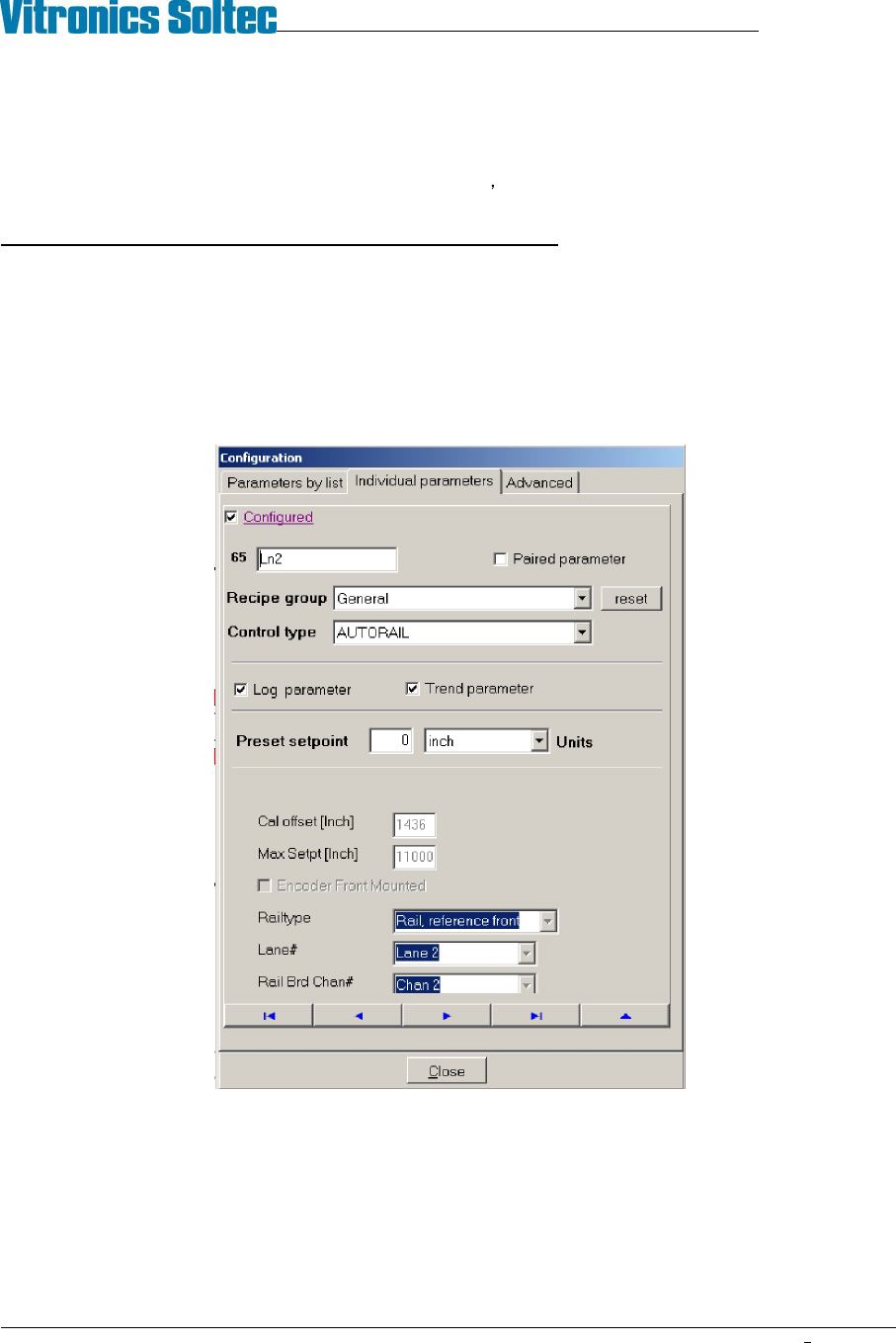
1. The PC oven software is configured correctly. The correct lane number, and axis type is specified for an axis.
The valid choices for lane number are 1 or 2. The axis type determines how and what direction the oven
controller moves and axis. The valid selection choices for axis type are moveable rail reference front,
moveable rail reference rear, board support 1 or board support 2. To view this configuration will require the
highest level of password. The configuration can be viewed under the Vitronics Soltec menu. Go to
Configuration, Parameters, Individual Parameters. Click on the button with the blue arrow pointing to the right
until you come to the parameter you wish to view.
An axis will always reference at its fixed rail location by moving towards the fixed rail until the in limit switch
input is encountered and then moving away from the fixed rail in the opposite direction until the in limit switch
input is present again. Each quadrature counter is cleared or reset to zero when a rail axis is set to its in limit
switch and then moved away from the in limit switch until the in limit switch signal is present again. This is
considered the true reference position for an axis. Because the make contact distance for a limit switch can
vary due to the large amount of over travel built into the switch mechanism, but the break contact distance is
relatively constant and therefore more accurate to use as a reference.