XPM2_XPM3 Technical Ref Manual Conveyor1.pdf - 第49页
VI TRO NICS-SOLTEC REFLO W SOLDERING SYSTEMS Oc tober 10, 2008 49 XPM 2 / XPM 3 Technical Reference M anual C onv ey or Sy stem s 2. The cable ass embl y (315602 5) to the rotary encode is s ecurely connected. Each rotar…
VITRONICS-SOLTEC REFLOW SOLDERING SYSTEMS
October 10, 2008
48
XPM2 / XPM3 Technical Reference Manual Conveyor Systems
TROUBLESHOOTING:
The quadrature encoder used on the rail width adjust is not subjected to much mechanical stress because of the
slow rotating speed of the rail adjust lead screw and also due to the intermittent operation of the rail width adjust
hardware. A properly aligned quadrature encoder shouldn t wear out or need to be replaced.
If an auto rail position fails to count or update verify the following:
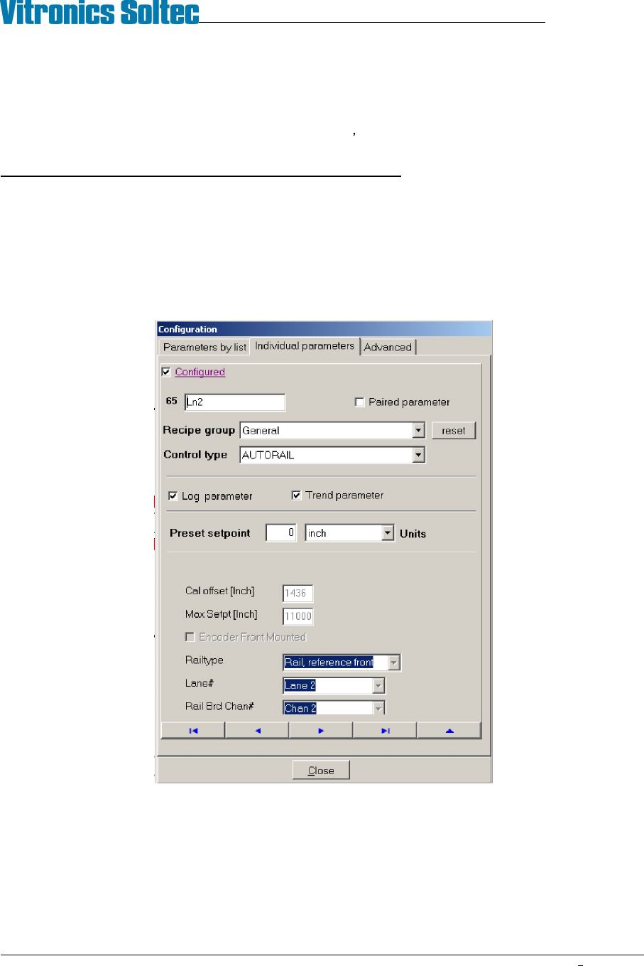
1. The PC oven software is configured correctly. The correct lane number, and axis type is specified for an axis.
The valid choices for lane number are 1 or 2. The axis type determines how and what direction the oven
controller moves and axis. The valid selection choices for axis type are moveable rail reference front,
moveable rail reference rear, board support 1 or board support 2. To view this configuration will require the
highest level of password. The configuration can be viewed under the Vitronics Soltec menu. Go to
Configuration, Parameters, Individual Parameters. Click on the button with the blue arrow pointing to the right
until you come to the parameter you wish to view.
An axis will always reference at its fixed rail location by moving towards the fixed rail until the in limit switch
input is encountered and then moving away from the fixed rail in the opposite direction until the in limit switch
input is present again. Each quadrature counter is cleared or reset to zero when a rail axis is set to its in limit
switch and then moved away from the in limit switch until the in limit switch signal is present again. This is
considered the true reference position for an axis. Because the make contact distance for a limit switch can
vary due to the large amount of over travel built into the switch mechanism, but the break contact distance is
relatively constant and therefore more accurate to use as a reference.

VITRONICS-SOLTEC REFLOW SOLDERING SYSTEMS
October 10, 2008
49
XPM2 / XPM3 Technical Reference Manual Conveyor Systems
2. The cable assembly (3156025) to the rotary encode is securely connected. Each rotary encoder has a finger
release on the connector to disconnect the 5pin cable assembly from the encoder.
3. Verify the continuity of the encoder cable assembly 3156025.
Wire Color A1-P46 or
A1-P47 Pin #
5 Pin Connector
on Encoder Pin #
Description
Red 1 4 5 VDC
Green 2 3 A channel output signal
White 3 5 B channel output signal
Black 4 1 0V dc common
Shield 5 No connection Shield
- - 2 Index output signal (not
used)
4. Monitor the output signals on the 5pin connector on the A1 board for each encoder in question.
5. The channel A and channel B outputs should transition from 0v to 5v while a lead screw is rotating and 5v
power should be present between pin 1(-) and pin 4(+) on the 5 pin connector on each encoder.
6. Verify that the plastic encoder disk is secured firmly on the lead screw by the set screw in the mounting collar.
7. Refer to the attached encoder manufactures instructions to verify the alignment of the encoder using the
alignment tool supplied by the manufacturer to properly align the plastic optical disk with the sensor assembly.
8. Replace the encoder assembly (1480801) if the output signals do not transition correctly or if the plastic optical
disk appears to be damaged.

VITRONICS-SOLTEC REFLOW SOLDERING SYSTEMS
October 10, 2008
50
XPM2 / XPM3 Technical Reference Manual Conveyor Systems
DC DRIVE CALIBRATION (RAIL WIDTH ONLY)
1.
Definitions-
A DC drive is actually a DC voltage amplifier. A small signal is sent to the drive and a large voltage is
sent to the motor. The typical DC drive uses an AC power source of 120 or 240 volts.
The set of controls found on a DC drive is:
A. Minimum speed adjust
B. Maximum speed adjust
C. IR comp
D. Torque
E. Signal
2.
What do the controls do?
A. Minimum speed adjust -- adjusts the minimum voltage output of the DC drive at the minimum-
input value. This value is typically 0 - 10% of the maximum input voltage.
B. Maximum speed adjust not used.
C. IR comp -- this adjusts the feedback circuit from the output of the DC drive. If the output voltage
drops, the IR comp circuit senses the drop, and more power is fed to the motor. This function is
preset to a value that covers 90% of all applications.
D. Torque -- this limits output current, and should only be adjusted by experienced people.
G. Signal -- signal adjust is found on DC drives which provide an option of being controlled by a
computer. If the DC drive is adjusted by a speed control potentiometer, signal or signal adjust has
no function.
Note: A DC drive with computer control will have a signal/manual selector switch or jumper. If the input
does not match the input selected, the DC drive will not operate correctly.
If a computer controls the DC drive, the maximum adjustment potentiometer will have no function.
3. Additional useful information
A. Always recalibrate when any component of a control system is changed.
B. Conveyor speed can be calibrated to specific requirements. This takes practice, but can yield
greater speed accuracy.
C. The conveyor speed should be measured with a stopwatch every sixty days.
D. Motor brushes wear out.
E. Calibration values may change with the age of the system.
F. Always record the adjusting potentiometer settings before replacing or calibrating a DC drive.
G. When replacing a DC drive, record the potentiometer settings; draw a sketch of the wire hookups;
make sure all wires have labels.