XPM2_XPM3 Technical Ref Manual Conveyor1.pdf - 第33页
VI TRO NICS-SOLTEC REFLO W SOLDERING SYSTEMS Oc tober 10, 2008 33 XPM 2 / XPM 3 Technical Reference M anual C onv ey or Sy stem s 8. Mov e the lane 2 f ix ed rail: Loosen the lane 2 fi xed rail end plate clamp screw s an…
VITRONICS-SOLTEC REFLOW SOLDERING SYSTEMS
October 10, 2008
32
XPM2 / XPM3 Technical Reference Manual Conveyor Systems
DUAL LANE DUAL XCS
The dual lane dual XCS conveyor system consists of two complete edge rail / XCS rail systems sharing a common
set of width adjust feed screws. Because the moveable components of the two lanes are coupled to the same
feedscrews the width and XCS position of the front and rear lanes remain identical.
DUAL LANE DUAL XCS LANE SPACING ADJUSTMENT
The distance between the two lanes is fixed at the factory. Adjustment of the lane spacing dimension is
accomplished by indexing (rotating) the acme nuts in the rail support plates of the front lane. The indexable nuts
are installed in the front lane rather then the rear lane to improve access to the adjusting mechanisms inside the
tunnel at the intermediate positions.
If starting with a conveyor that is not properly qualified, set the lane to lane spacing between the pair of rails on
each feed screw using the indexable Acme nuts (ref. steps 9 & 10 below), then refer to ALIGN AND PARALLEL
EDGE RAILS to set lane parallel.
If starting with a dual lane conveyor system that is properly set up and qualified, the most efficient method of
changing lane spacing is to move each rail an exact amount w/in ±.005 (±0.13mm) as follows:
1. Measure and record the distance from one fixed rail extrusion to the other at every attachment point
(onload, offload, gantry and intermediates). It does not matter what face of the rails is used for the
measurement as long as you are consistent.
2. Repeat step 1 for the moveable edge rails.
3. Repeat step 1 for the XCS rails.
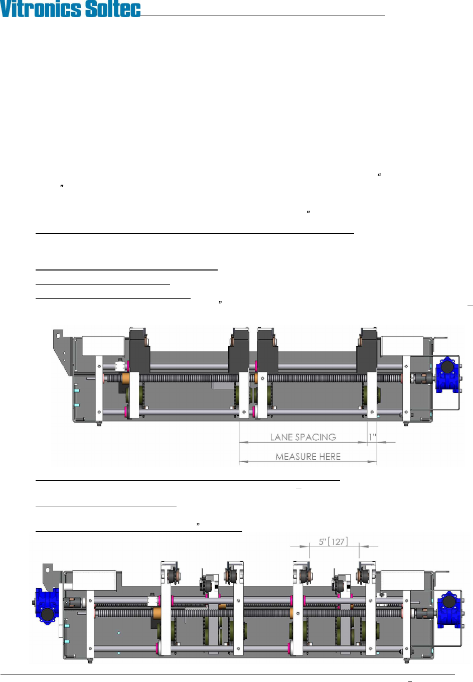
4. Determine the current lane spacing: At the onload end measure the distance between the outside surfaces
of the two fixed rail end plates. Subtract 1 (25.4mm) from this measurement (example: 361.95mm
25.40mm = 336.55mm).
5. Calculate the amount all affected conveyor components need to move: Subtract the desired lane
spacing from the current lane spacing (example: 336.55mm 251mm = 85.55mm).
6. Establish the target lane settings: Subtract the amount to be moved from each of the width
measurements taken in steps 1 through 3.
7. Set the lane width at approximately 5 (125mm) using the conveyor width system.
VITRONICS-SOLTEC REFLOW SOLDERING SYSTEMS
October 10, 2008
33
XPM2 / XPM3 Technical Reference Manual Conveyor Systems
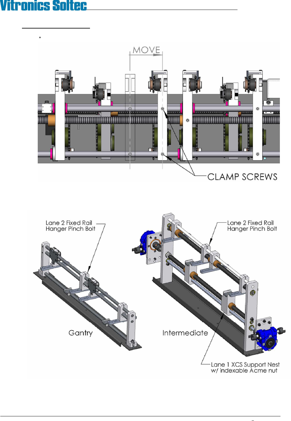
8. Move the lane 2 fixed rail: Loosen the lane 2 fixed rail end plate clamp screws and corresponding pinch
bolts in each gantry and intermediate rail hanger, then move the lane 2 fixed rail to the target dimensions
(±.005 ) calculated in step 6.
VITRONICS-SOLTEC REFLOW SOLDERING SYSTEMS
October 10, 2008
34
XPM2 / XPM3 Technical Reference Manual Conveyor Systems
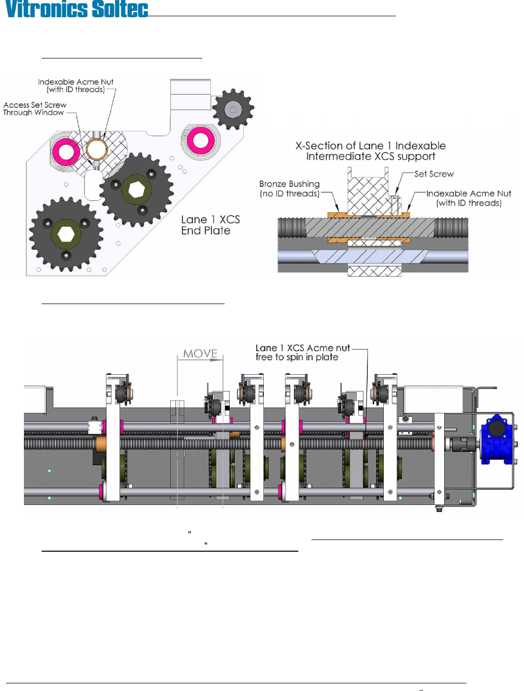
9. Decouple the lane 1 XCS Acme nuts by loosening the set screws in the onload and offload XCS end plates
and intermediate support nest(s).
10. Move the lane 2 XCS toward the fixed rail by operating the XCS width adjust system. Make the move in
small increments, stopping to rotate the indexable XCS Acme nuts in lane 1 so that the rail stays straight
and the XCS chain does not run into the fixed rail. It may be necessary to temporarily remove the XCS
chain and rail from lane 1 while performing this step.
11. Once the XCS is approximately 1 (25mm) from the fixed rail adjust each of the lane 1 XCS Acme nuts to
achieve the target dimensions (±.005 ) calculated in step 6. Be very careful to not over tighten the set
screws when locking the adjustable Acme nuts in position. It is very easy to distort the Acme threads
enough to bind the nut on the feedscrew.