XPM2_XPM3 Technical Ref Manual Conveyor1.pdf - 第39页
VI TRO NICS-SOLTEC REFLO W SOLDERING SYSTEMS Oc tober 10, 2008 39 XPM 2 / XPM 3 Technical Reference M anual C onv ey or Sy stem s DRIVE MOT OR S ERVICE & REPLA CEMENT Con v eyor Driv e Motor Replace m ent - MOTOR LOC…

VITRONICS-SOLTEC REFLOW SOLDERING SYSTEMS
October 10, 2008
38
XPM2 / XPM3 Technical Reference Manual Conveyor Systems
If the conveyor motor does not rotate, check the following:
Verify that the conveyor is switched on in the PC oven software.
Verify that K37 is energized and that A1-K8 is also energized.
Verify that 120 VAC is present at the G5 power supply or verify that the green LED on the front of the power
supply is on.
If 120VAC is not present then make sure that A1-K8 is energized on the A1 board, that F68 is not tripped and
that the inrush current limiter on pins 1 and 2 of connector P52 on the A1 board are intact.
Verify the analog voltage reference signal to the A42 board.
The signal should be +10 VDC between pins 1(+) and 2 (-) on connector P2 of A42 when the analog output is
at full scale.
If there is no signal present, make sure that the controller rack has +15 VDC at pin 4 of connector P26 of the
A1 board. (-15 is not present or required on the new controller)
If +15 VDC is present , but the drive is not receiving +10 VDC, there is either a wiring error or the DI board is
faulty, or a poor wire connection.
If motor turns, but no speed is reported, check the following:
Verify that the hex drive shaft is rotating.
Verify that the sprocket installed on the hex drive shaft is also rotating.
Verify that LED2 on A42 is flashing as each sprocket tooth from the sprocket on the hex drive shaft passes by
the fork shaped sensor on A42.
If LED2 is not flashing on A42 and the hex shaft and sprocket are rotating then perform the following:
Verify the alignment of the sprocket with the fork shaped sensor on A42. The sensing area on the fork shaped
sensor is on the top most edge of the sensor and only the tips of the sprocket teeth should be extending into
the opening on the sensor. If the sprocket teeth extend too far the sensor won't detect the gaps between each
sprocket tooth and will sense the hub around the sprocket teeth instead.
If LED2 on A42 does not light or never changes state then test the following.
Verify that 5VDC is present between pins 1(+) and 3(-) of connector P3 on A42. The 5VDC is required to
operate the logic components on A42.
If the polarity is reversed or if connector P1 and P3 are reversed on A42 then A42 will have to be replaced
after the wiring has been corrected. Because reverse polarity and or 24VDC will permanently damage all of
the logic components on A42.
If 5VDC is present and LED2 on A42 still doesn't change state then perform the following:
Shut off the conveyor motor.
Unplug connector P4 from A42.
Loosen and remove the (2) 1/4-20 bolts that secure the bracket that A42 is mounted on to the front of the rail
width gearbox.
With the A42 assembly separated from the sprocket on the hex drive shaft pass a small object back and forth
between the top most tip of the fork sensor while observing LED42 on A42.
A pen or the tip of your finger can be used.
If LED2 still does not change state and 5VDC is present between pins 1(+) and 3(-) of connector P3 on A42
then A42 is defective and needs to be replaced.
After the conveyor system has been repaired, run the conveyor calibration routine in the Oven Control Program.
VITRONICS-SOLTEC REFLOW SOLDERING SYSTEMS
October 10, 2008
39
XPM2 / XPM3 Technical Reference Manual Conveyor Systems
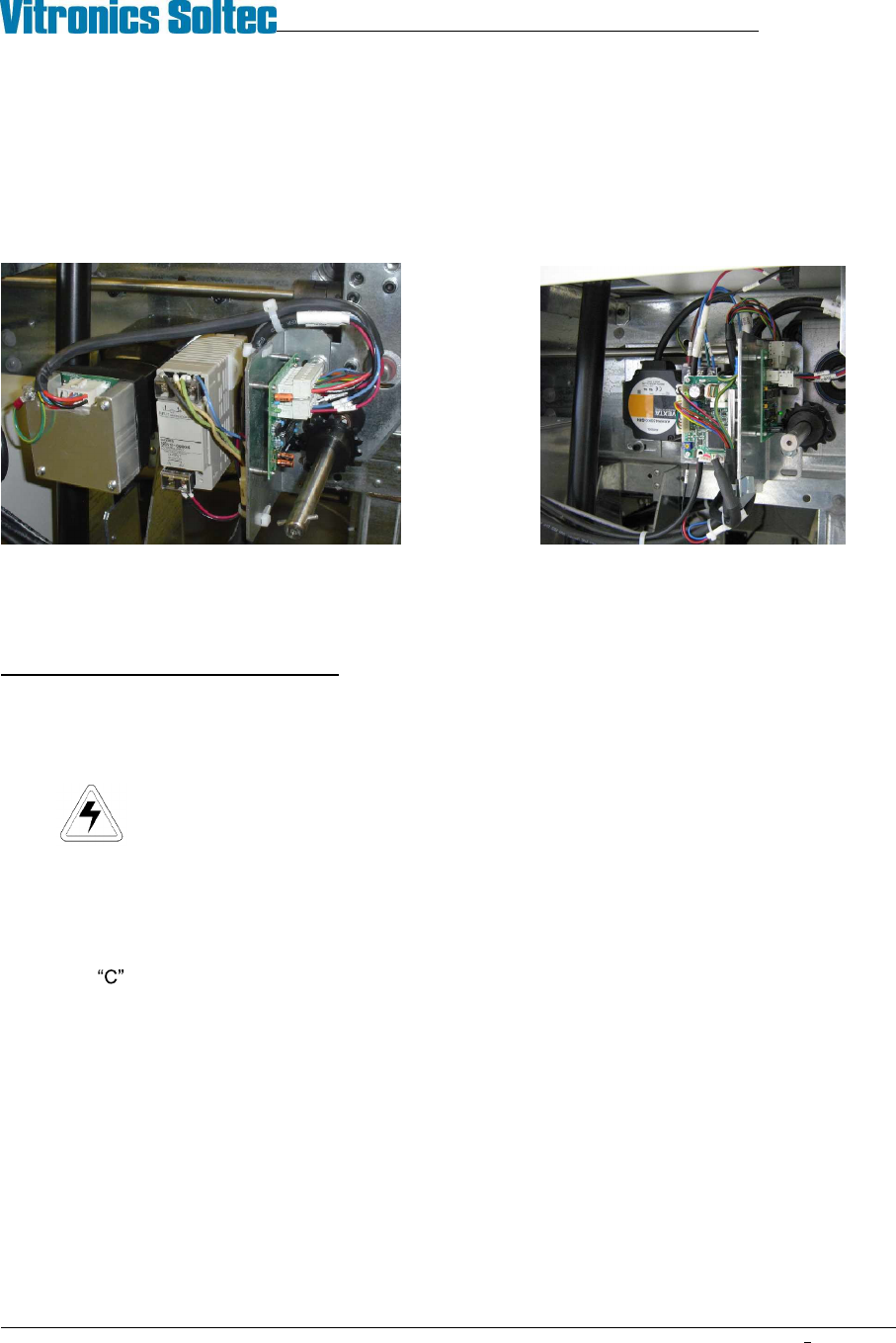
DRIVE MOTOR SERVICE & REPLACEMENT
Conveyor Drive Motor Replacement - MOTOR LOCATION
There are only two locations for the conveyor motor on all Vitronics-Soltec Reflow Ovens. On an oven with a left
To right conveyor, the motor assembly is in the front right corner of the oven. On an oven with a right to left
conveyor system, the motor assembly is on the front left corner of the oven.
Integra Motor Oriental Motor
CONVEYOR MOTOR REPLACEMENT
To remove/replace the Conveyor Drive Motor:
1. Open the Hood
2. Turn off the U.P.S. and disconnect all power from the oven.
3. Remove the sheet metal at the exit end of the end the oven to gain clear access to the motor and
components.
4. Remove the G5 power supply
5. Unplug the cable from the motor.
6. The Motor is attached to a mounting plate with four bolts. That plate is mounted with four bolts on the Oven
Frame Channel. Loosen the four bolts and slide the plate to the exit end of the oven. This will allow the
Chain to be removed from the Drive Sprocket without removing the Master Link from the Chain.
7. While supporting the Motor, remove the four bolts. Remove the motor, mounting plate and sprockets from the
Oven.
8. Rotate the Motor to permit access to the setscrews that secure the drive sprocket to the Motor Drive Shaft.
Loosen the setscrews and remove the sprocket, then remove the Motor from the mounting plate.
9. Install the new motor and drive sprocket on the mounting plate.
Reverse steps 7 through 1 to replace the Conveyor Drive Motor
Left to Right Conveyor
VITRONICS-SOLTEC REFLOW SOLDERING SYSTEMS
October 10, 2008
40
XPM2 / XPM3 Technical Reference Manual Conveyor Systems
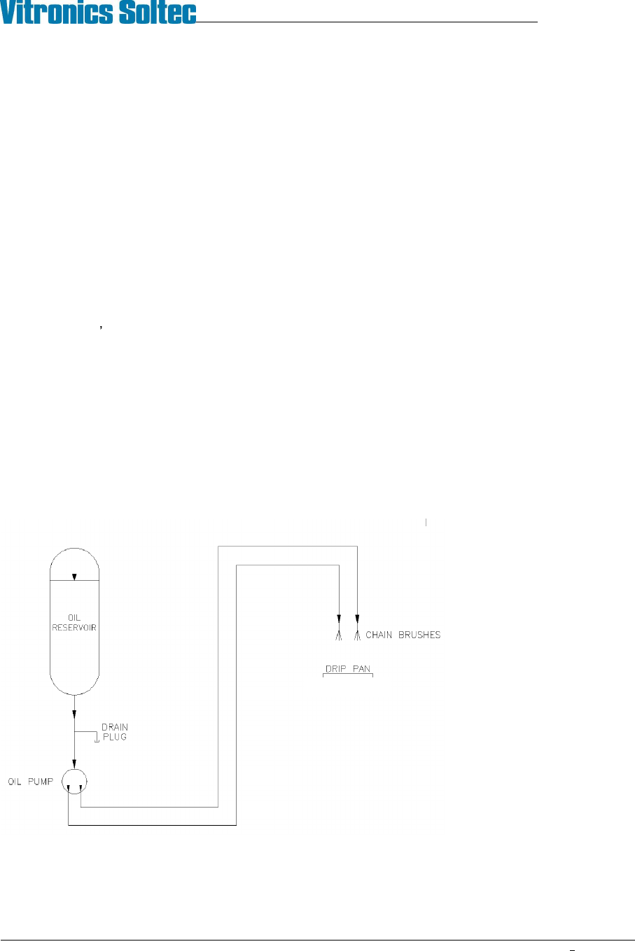
COMPUTER CONTROLLED EDGE-RAIL LUBRICATION
Computer Controlled Edge-Rail Lubrication is:
!
Standard, (installed on all ovens)
)
An option, (NOT installed on all ovens)
DESCRIPTION:
The edge-rail lubrication system is designed to improve the lifetime of the rail chain conveyor by periodically
applying lubrication to the chain during oven operation.
Two modes of lubrication are available, automatic and manual. Systems with automatic chain lubrication are also
capable of performing manual chain lubrication, initiated by the operator, through the Oven Operation Program.
OPERATION:
fi Following the enabling of an output from the controller, the system pumps oil from the reservoir, through
tubing, to stainless steel brush/wheels which are touching the chain and the oil is applied to the chain.
fi It is the user s responsibility to ensure that this reservoir is always filled with the required lubricant. The
system generates a warning message when it calculates that the oil in the reservoir is getting low.
fi The lubricant type is DARMEX OIL # 773ND
During the lubrication process, the oil is applied for two complete cycles of the chain. The user may determine the
number of chain cycles between automatic lubrications. 275 is the default number.
The number of complete lubrications held within one reservoir is set to the factory default of 50. The system will
display a warning whenever it calculates that the reservoir level is getting low when the number of lubrication
cycles that have occurred reaches the tank count number in the lubrication setup screen. Since the amount of oil
dispensed in one application is system dependent, the number of complete lubrications is best found by trial and
error.
Construction:
The Auto Chain Lube System
consists of a 1 quart
polypropylene oil reservoir,
drain plug, electrically powered
pump, tubing for oil
distribution, and two stainless
steel brushes for the
application of lubricating oil
directly to both oven conveyor
chains.
Auto Chain Lube System Schematic