presto_en.pdf - 第13页
Page 13 2.4.5 Programming Interface Devices t o be programmed are connec ted t hrough a 8-pin ISP conn ector, wh ich is ba ckward compat ible with the ICSP c onnector for PIC microcon trollers. 2.4.6 Power Supply From Ap…

Page 12
2.4
Use
PRESTO is a fast USB programmer suitable for
programming of a range of devices such as
microcontrollers, EEPROM or Flash serial memory chips,
CPLD, FPGA and many others. It is equipped with
overcurrent protection at the VDD and VPP sources and
with overvoltage protection at the VDD pin.
The programmer is powered via USB. It can feed the
application to be programmed with a voltage of 5V or it
can utilize an external application’s voltage of 2.7V to
5.5V during programming.
The programmer may run under WindowsXP or later.
2.4.1 Numerous Supported
Devices
The list of supported devices includes:
• Microchip PIC microcontrollers – devices with serial
programming, which include all PIC and dsPIC devices
with the exception of several obsolete types.
• Atmel AVR microcontrollers – all devices supporting
"SPI Low Voltage Serial Downloading" such as
ATtiny12, AT90S8535 or ATmega128.
• Atmel ATxmega microcontrollers – devices
programmable via JTAG interface such as
ATxmega128A1.
• Atmel AVR32 microcontrollers – AT32UC3A1256, for
example.
• Atmel 8051 microcontrollers – devices that support
ISP programming such as AT89S8253, AT89LP4052,
AT89LP216 or AT89S2051.
• Texas Instruments microcontrollers – 16-bit MSP430,
CC430 (fuse programming is not supported for these
families) and CCxxxx.
• Cypress – PSoC microcontrollers.
• Serial EEPROM and Flash memory chips - I2C
(24LCxx), Microwire (93LCxx) and SPI (25Cxx).
• Devices with JTAG interface, for which an SVF or an
XSVF file can be created. These include CPLD (such as
Xilinx XC95xx and CoolRunner), configuration memory
for FPGA (such as Xilinx XC18Vxx and XCFxxS),
microcontrollers (such as ATmega128) and others.
This, however, is not an exhausting list of possibilities.
Additional types are regularly supplemented in response
to customers’ interest. New software versions are
downloadable from the Internet for free.
2.4.2 USB Connection
PRESTO is controlled and powered through a USB port. It
communicates in the Full-Speed mode and works with a
USB 2.0 port or a USB 1.1 port. This means that
connecting the programmer is fast and easy, requiring
only a single cable.
2.4.3 Programming of
Placed Devices
ISP (In-System Programming) or the special ICSP (In-
Circuit Serial Programming) for the PIC microcontrollers is
currently replacing the traditional method in which
devices were first programmed and only then placed on a
PCB (printed circuit board). Thanks to ISP even SMD
devices with an extremely narrowly spaced pins can
easily be programmed and their firmware upgraded in
already assembled and finished devices.
2.4.4 Programming of
Autonomous Devices
Those who still need to program autonomous devices, i.e.
devices not yet placed on a PCB can use the ISP2ZIF
adapter featuring a ZIF (zero insertion force) socket.

Page 13
2.4.5 Programming
Interface
Devices to be programmed are connected through a 8-pin
ISP connector, which is backward compatible with the
ICSP connector for PIC microcontrollers.
2.4.6 Power Supply From
Application
The VDD output can serve as an input using the power
from the application for feeding the output buffers with a
voltage from 2.7V to 5.5V or it can become an output
and as such to provide voltage for the application.
PRESTO can power applications with 5V voltage.
PRESTO detects three levels of external power supply
voltage: 3V, 5V and overvoltage.
PRESTO includes an overcurrent protection at pins P and
VDD.
The voltage range can be extend by two optional
adapters (HPR3V3, HPR1V2).
HPR3V3 is an optional accessory for PRESTO by which
PRESTO can power applications with 3.3V voltage.
HPR1V2 is an optional accessory for PRESTO which
extends input voltage of VDD pin in power from
application mode from 1.2V to 3.3V.
2.4.7 User Interface
The programmer status is clearly indicated by two LEDs.
ON-LINE (green LED) informs of connecting to USB while
ACTIVE (yellow LED) signals an activity of the
programming interface.
The GO button significantly increases the operator’s
comfort in repeated programming. It starts programming
or other user-defined commands.
2.4.8 Software
The UP program is a basic software tool for working with
PRESTO, also compatible with the FORTE programmer.
Apart from standard commands, UP provides numerous
above-standard functions, which broaden the
programmer’s applications and simplify its operation.
These include the possibility to define projects, existence
of adjustable parameters when running from the
command line providing for unattended programmer
operation in routine programming, environment
personalization incl. keyboard shortcuts, automatic
generation of serial numbers, etc.
UP has been developed for WindowsXP or later.
Modified drivers developed by FTDI are used for
communication through USB.
Devices with the JTAG interface, for which an SVF or an
XSVF file can be created, can be programmed by means
of the JTAG SVF Player software.
The voltage at the VDD pin is permanently displayed in
UP for greater comfort and for monitoring of the
operation. The reset signal is conveniently controlled by a
single button.
2.4.9 Debugging
PRESTO provides user with support for debugging ARM
microcontrollers through OpenOCD which is an open
source debugging system originally developed by
Dominic Rath. OpenOCD uses GDB for access to debug
functions. User can communicate with OpenOCD via a
command line and telnet.
The revision 717 of OpenOCD, which can be found on our
website in a program package together with the ARMINE
program, is supported officially.
Page 14
2.5
Controls and
Connectors
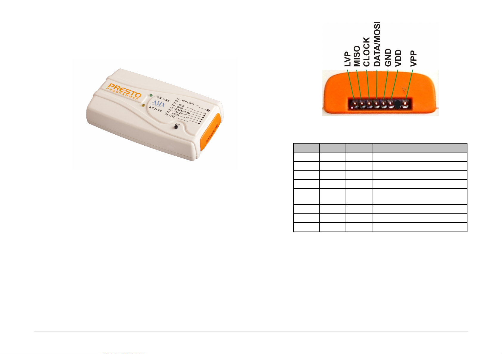
Fig.2: The PRESTO programmer
PRESTO features two LEDs, a button, a connector for
linking to USB and a programming connector.
2.5.1 Programming
Connector
The programming connector is a 8 way single row plug
with pin No.2 (in standard numbering) missing. Spacing
between pins is 2.54mm.
Fig.3: Programming connector
Pin
Name
Type
Description
P1
VPP
I/O, VPP
signal input/output or VPP output
P2
key
P3
VDD
PWR
power input/output
P4
GND
PWR
signal grounding
P5
DATA/
MOSI
I/O
signal input/output
P6
CLOCK
O
signal output
P7
MISO
I
signal input
P8
LVP
I/O
signal input/output
Table1: programming connector
2.5.2 GO Button
his button simplifies work with the application being
programmed. It triggers device programming or another
pre-programmed function. For further information on
settings see
Setting the GO Button