presto_en.pdf - 第39页
Page 39 sn2: 00004 5566778, 21000202 0304; sn3: 00005 6677889, 21000302 0304; note sn4: 00006 778899A, 21000402 0304; sn5: 00007 8899AAB, 21000502 0304; sn6: 00007 8899AAB, 2…

Page 38
The numbers themselves are logged in case of calculated
serial numbers while their labels are logged in case of
serial numbers taken from a file - see
Format of Files with
Serial Numbers
.
Except for the serial numbers also the date, time and the
result of the programming are writen to the file. For the
devices for which the revision reading is supported, the
revision number is also written to the file.
Format of Files with Serial
Numbers
Files containing definitions of serial numbers are text files
that can easily be created in third-party programs. *.SN or
*.TXT are recommended file extensions.
A serial number record has the following form:
[comment] label: data record, data record, ...,
data record;
Semicolons are obligatory at the end of records.
• Comment is any string containing no colon ':'.
Comments are optional. If a colon cannot be found in
the whole serial number record, the record is ignored
(understood as a comment). It is also possible to write
a comment behind two slashes '//'.
Thisisjustacomment;
//Alsothisisacomment.
• White character is a space, tabulator or end of line
(CR+LF).
• Label is a string identifying the serial number. This
string is compulsory. The label must not contain white
characters, colons or semicolons.
Data Record
A data record consists of an address and data items in a
chain following this address.
Each item can be written in hexadecimal form (e.g. 2100)
or a numeral base in which the number is written in can
be explicitly defined.
For example, b'10101010' means the same as h'AA',
d'170' or just AA. 'A' means d'65' (ASCII character itself).
ExamplerecordforPIC16F628A:
2100 05 55 54 means to save data 05h, 55h, 54h in
addresses 00 to 02 of a data memory.
The code/main memory which stores the serial number
can also be specified by the word “CODE.” or “PROG.” or
just “P.”.
The data memory should be specified by the word
“DATA.” or “EE.” or just “E.”.
“ID” or just “I” is used for the memory of ID positions.
These words are always followed by an address inside the
specified memory.
Example:
EE.00 05 55 54 means to save data 05h, 55h, 54h in
addresses 00 to 02 of a data memory.
Notes
• * There is no specifier for the configuration memory, it
would make no sense.
dsPIC – addresses of 24-bit words are to be written in for
all addresses (i.e. an internal dsPIC address of 24h is 12h
here). For a data (EEPROM) memory addresses of 16-bit
words are to be written in, i.e. as they go one by one
through the microcontroller.
• Autonomous memory chips (I
2
C, SPI) have only the
code memory. If a non-existent memory is specified,
an error is reported.
Example of File with Serial Numbers
Commentatthebeginning;
sn1: 000034455667,
210001020304;serialnumber1
Page 39
sn2: 000045566778,210002020304;
sn3: 000056677889,210003020304;
note
sn4: 00006778899A,210004020304;
sn5: 000078899AAB,210005020304;
sn6: 000078899AAB,210006020304;
sn7: 000078899AAB,210007020304;
sn8: code.00013F003F013F023F03,
data.0002'x''4''2';
sn9: prog.00013F003F013F023F03,
e.0002'x''4''3';
5.4.4 Calibration Memory
Support
Some devices contain a calibration memory containing
factory-preset device calibration. The loss of its content
can cause a fault in the device functionality. For this
reason we have tools allowing users to work with the
calibration memory.
Working with Calibration
Memory When Erasing a Device
in UV Eraser
Calibration data should be saved prior to erasing a
device. To do so, choose File ➙ Save calibration
data...
ou can retrieve it back by choosing File ➙ Read
calibration data...
The program contains a function for verifying whether a
device has been erased correctly: Device ➙ Blank
check. When this command is used, the program displays
data from the calibration memory.
Working With Calibration
Memory in Devices With Flash
Memory
When these devices are erased, the content of their
calibration memory is preserved.
If you really need to erase the calibration memory for
some reason, you can do so by choosing Device ➙ Erase
➙ Erase all (including calibration).
Advice
New Flash devices with a calibration memory (such as
PIC12F629) contain so called 'bandgap bits', which form
part of the device calibration. These bits can be found in
the configuration word and are erased too if the
command Device ➙ Erase ➙ Erase all(including
calibration) is executed!
5.5
Program Controls
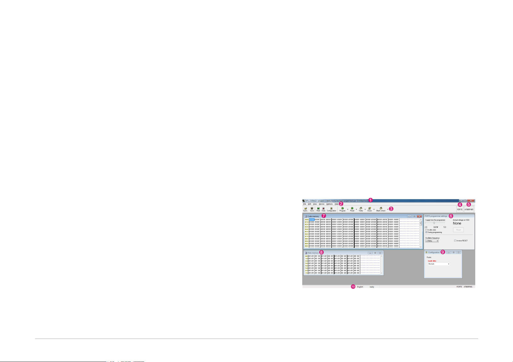
Fig.25: Controls of UP software
1) Title bar with the open project name or file
2) Menu

Page 40
3) Toolbar
4) Currently selected programmer
5) Currently selected device
6) Programmer settings window
7) HEX editor window for code/main memory
8) HEX editor window for data memory
9) Configuration window
10) Status bar
5.5.1 Toolbar
A toolbar is a panel with quick selection buttons located
under the program menu (see
Program Controls).
If you want to remove the toolbar, simply uncheck the
Display icons and descriptions on the toolbar button
options in the Settings menu as described in
Program
settings
.
5.5.2 Status Bar
The status bar is a panel in the bottom part of the window
(see
Program Controls). It presents information on the
programmer, the device, changes to the file since the last
saving, etc.
Individual parts of the status bar react to double-clicking
and to the context menu that opens after right-clicking.
If you want to hide or re-display the status bar, choose
Program settings ➙ Panels ➙ Display the status bar
in the lower part of the window.
5.5.3 Menus
The following texts describe in detail individual items in
the UP software menus.
Menu commands can be triggered with mouse by clicking
on a particular menu item or from the keyboard by
pressing the key together with the shortcut, i.e. the
underlined letter in the menu.
The menu bar consists of the following menus
(categories):
•
File Menu
•
Edit Menu
•
View Menu
•
Device Menu
•
Options Menu
•
Help Menu
File Menu
File ➙ New
Keyboard shortcut: Ctrl+N
The program creates a new empty file. If the currently
open file has not been saved, the program prompts the
user to save it.
File ➙ Open...
Keyboard shortcut: Ctrl+O
The program opens the Windows standard dialog listing
the files saved on the disc. The supported file formats are
described in
Appendix C: Intel-HEX File Format. Files with
extensions .hex or .a43 are loaded as Intel-HEX, others as
binary. There are also filters available making it possible
to open all files as .hex or as .bin.
File ➙ Open next file...
The program imports another .hex or .bin file with an
optional offset. This function is useful if the user needs to
load another file into device's memory. Files with
extensions .hex or .a43 are loaded as Intel-HEX, others as
.bin.
For example, this command provides for merging of
several .hex files (e.g. bootloader + program).