presto_en.pdf - 第19页
Page 19 4) After the device fuses are correctly set up, right- click (i.e. u sing the right mouse b utton) inside th e Configuration window and c hoose Learn fuses . This saves t he fuses in t he up.ini file or in the pr…
Page 18
2) The whole device must be erased before
programming if code/main memory protection (CP) or
data memory protection (CPD) is active.
3) Some PIC devices cannot be erased with CP or CPD
active being powered by voltage less than 5V.
4) If a microcontroller has more than one power-supply
VDD or VSS pin, all of them must be connected
including the AVDD and AVSS pins.
5) PIC microcontrollers which require 3V or lower power
supply must be fed from external power supply
because PRESTO can only provide 5V voltage.
6) Some PIC microcontrollers require voltage less than
13V on the MCLR pin while the programmer can only
set 13V voltage level on VPP. If such device has been
selected in UP, a warning message is displayed. It is
recommended to limit voltage on the MCLR pin by an
external circuit (a potential divider or a Zener diode
and a resistor).
VPP
Resistor
9V
390Ω
11V
200Ω
Table6: Recommended resistors values with Zener diode (the
value also depends on the rest circuit)
7) If the LVP mode is used, it is recommended to check
whether the LVP fuse is still set after erasing the part.
8) Programming of PIC32 devices is supported by
means of the ICSP interface only with external 3V
power supply.
9) Devices with an ICPORT fuse must have the
dedicated ICSP port off for LVP programming.
10) PIC24 and dsPIC33 devices may be programmed
using PE (Programming Executive) or using the
standard method. Programming by means of PE is
usually faster.
11) Programming of some new PIC microcontrollers in the
HVP mode can cause that a warning message
indicating overcurrent on VPP appears. If that
message does not indicate a real fault it could be
caused by different technology which has been used
by Microchip for producing new devices, although
they are from pristine families. These devices have
slightly different parameters. It could be solved by
connecting capacitor of 1nF between the VPP pin
and GND and resistor of 10Ω in serial with VPP signal
if the fault persists.
12) When the MCU debug mode is enabled using a fuse,
the programmer cannot communicate with it.
AVR Microcontrollers
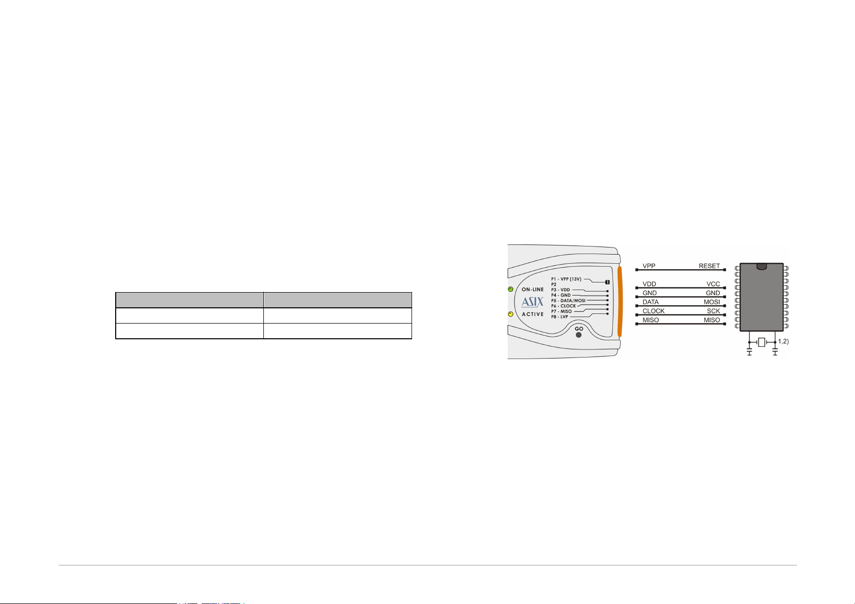
Fig.7: AVR microcontroller
1) A source of the clock signal, which is set in the device
or which will be set by fuses during programming
must be connected to the device. A crystal must be
connected if set up as the clock source.
2) Device fuses have been set up by the producer to the
internal oscillator with a frequency of 1MHz. In the
initial programming, the device should be
programmed with “Oscillator frequency” set up at
“>750kHz” or lower in the “PRESTO programmer
settings” window.
3) Not all AVR microcontrollers allow use of a crystal
(e.g.ATtiny13, ATtiny15).
Page 19
4) After the device fuses are correctly set up, right-click
(i.e. using the right mouse button) inside the
Configuration window and choose Learn fuses.
This saves the fuses in the up.ini file or in the project
if used. This is necessary due to the fact that .hex
files for AVR microcontrollers themselves do not
contain configuration fuses. If a device is
programmed from the command line, a .ppr project
file containing saved fuses needs to be used.
5) Ticking the Open file with data memory
automatically option in the File menu loads data
for the data memory simultaneously with the code/
main memory data.
6) Use the EESAVE fuse if preservation of data memory
is required. If the EESAVE is active, choose Program
all except data memory for programming,
otherwise a warning appears at this place (blank
check of data memory).
7) HPR3V3 is an optional accessory for programming
AVR microcontrollers which reguire 3.3V voltage with
PRESTO internal 5V power supply.
8) HPRAVR is an optional accessory for programming
AVR microcontrollers in applications with the
ISP10PIN standard connector on the device's side.
9) Some AVR devices have their ISP interface provided
at different pins than the SPI interface. Further
information can be found in the device data sheet (in
the Serial Downloading section).
AVR with TPI Interface (e.g.
ATtiny10)
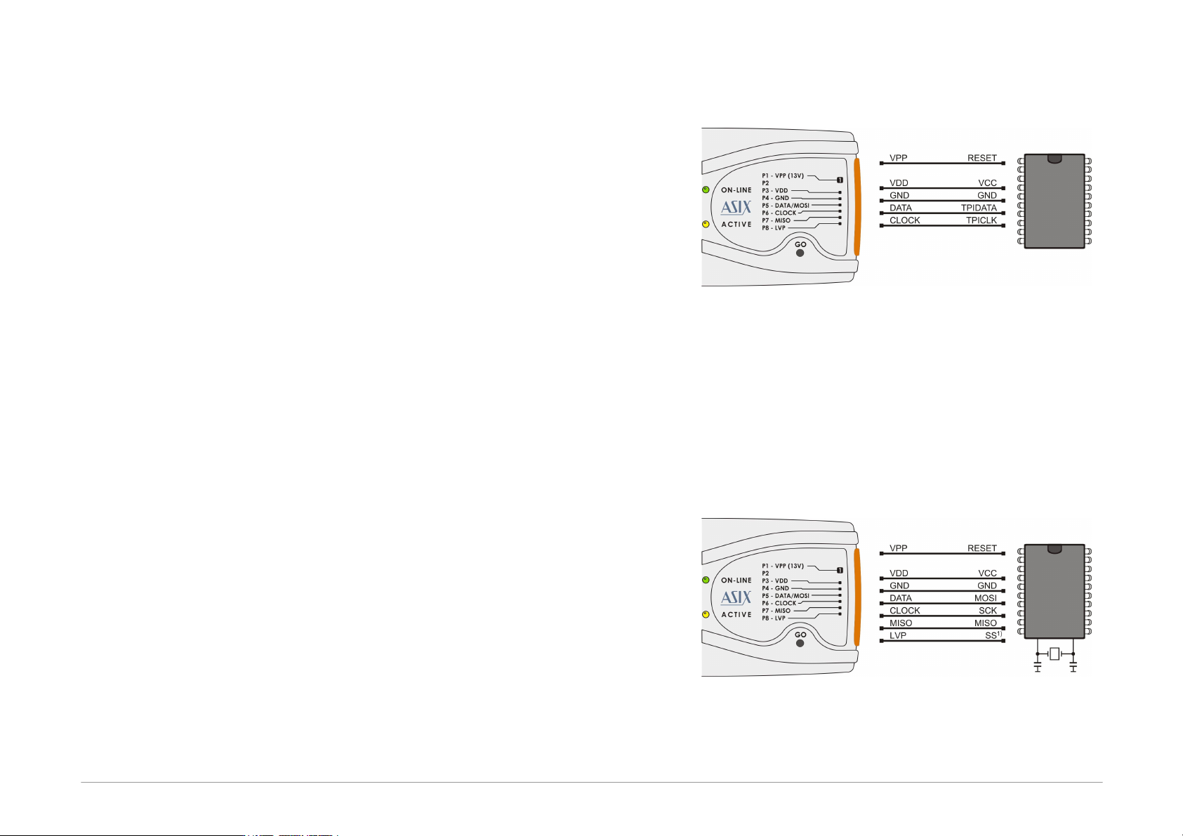
Fig.8: AVR microcontroller, TPI interface
1) These microcontrollers require voltage 12V on the
RESET pin during programming in the HVP mode
while the programmer can only set 13V voltage level
on VPP. Therefore it is necessary to limit voltage on
the RESET pin by an external circuit. There is no need
of any external circuit for the LVP mode which is
preferred.
Atmel 8051
Fig.9: Atmel 8051 microcontroller
Page 20
1) The SS pin must be connected only for AT89LP2052 /
4052 / 213 / 214 / 216 / 428 / 828 / 6440 / 51RD2 /
51ED2 / 51ID2 / 51RB2 / 51RC2 / 51IC2.
2) AT89LP213, AT89LP214 and AT89LP216 have the
inverse reset logic. Thus an appropriate resistor must
be pulled-up to VCC.
3) PRESTO can not program devices containing the
letter “C” in their name, however, it supports devices
with “S” in their name, of which some are compatible
with the “C” types. For example, AT89C2051 is not
supported, but AT89S2051 is.
4) The software assumes that while programming
AT89LP52, the device’s POL pin is in logical1. If POL
is in logical0, the Inverse RESET option should be
activated in the program. For AT89LP51RD2,
AT89LP51ED2, AT89LP51ID2, AT89LP51RB2,
AT89LP51RC2 and AT89LP51IC2 the software
assumes the POL pin in logical0.
Cypress PSoC
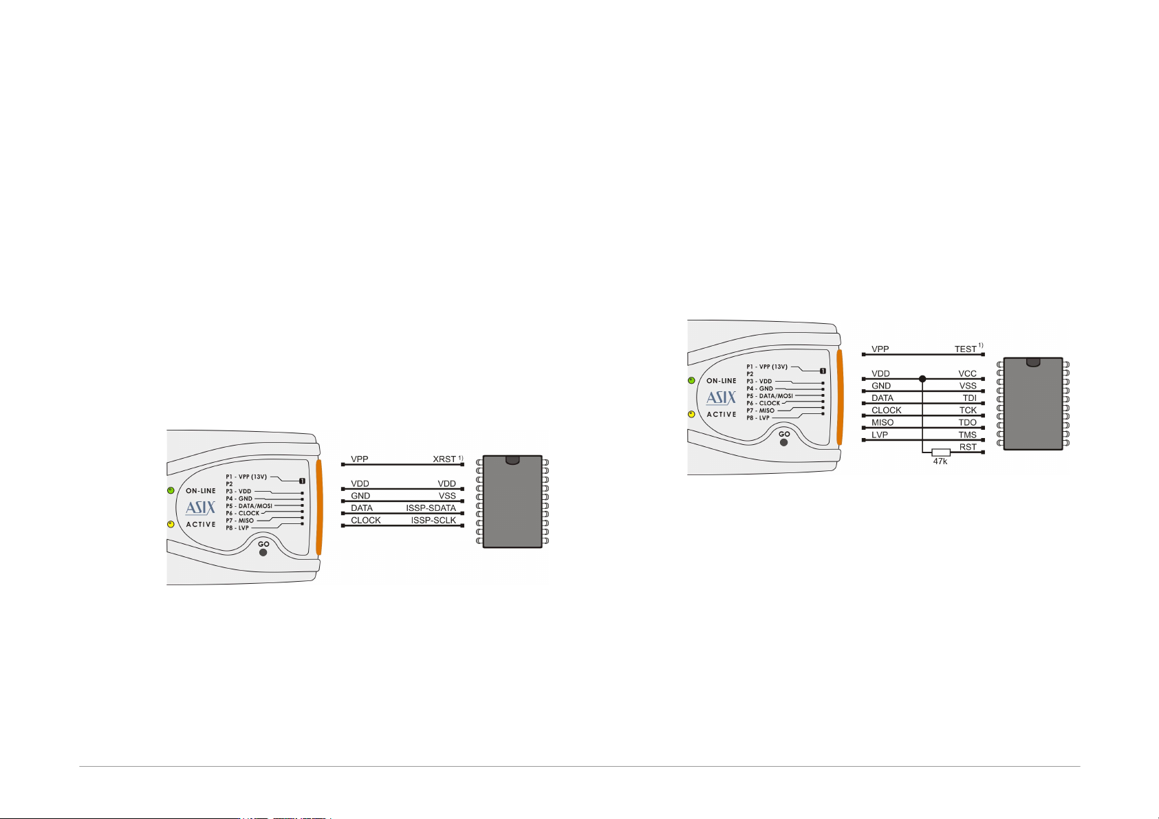
Fig.10: Cypress PsoC microcontroller
1) The way of entering in the programming mode
should be set in the PRESTO programmer settings
window. Devices without an XRST pin can only use
initialization through the power-on reset (by power
supply). Devices with an XRST pin may use both
methods, but the method using the reset signal for
initialization is better as it can be used in
combination with an external power supply.
2) Algorithm programming in the PRESTO
programmer settings window should be set in
accordance with the power supply cable used.
MSP430 with TEST pin without
SBW interface
Fig.11: MSP430 microcontroller, TEST pin, without SBW
1) Not all MSP430 microcontrollers have the TEST pin.
2) This interconnection can be used with e.g.
MSP430F1xx, MSP430F4xx, MSP430F21x1, but not
with MSP430F20xx or MSP430F22xx.
3) If the oscillator calibration values are saved in the
information memory and this memory is not going to
be re-programmed (erased) during programming, the
device should be programmed with the Cal Int. RC
(=calibrated internal RC oscillator) option selected in
the PRESTO programmer settings window. In the
other cases Not Cal Int. RC (=not calibrated internal
RC oscillator) should be selected.