presto_en.pdf - 第87页
Page 87 Notes Some AVR devices d o no t suppo rt page by page programming. In suc h a case, t he SVF file must be created withou t the -mp paramet er. Lattice CPLD Programming SVF file can be created from a .JED file usi…

Page 86
8
JTAG PLAYER
JTAG PLAYER is a utility designed for programming
devices with the JTAG interface by means of PRESTO or
FORTE programmers.
This utility is not part of the UP software installation pack
but it can be downloaded separately from
https://
www.asix.tech/prg_jtag-svf-player_cz.html
JTAG PLAYER is localized only in English.
8.1
JTAG Device
Programming
Having started JTAG PLAYER, select your programmer in
Options ➙ Select Programmer.
If you cannot see your connected programmer in the
dialog window, check if the green ON-LINE LED on the
programmer is on. If so, make sure thatanother software
is not communicating with the programmer.
Program the device by choosing File ➙ Open&Process.
The file to be programmed must be in SVF/XSVF format.
For more information on the file format see
SVF File or
XSVF File.
If an error occurs during the programming process, check
the connection between the programmer and the
application. In addition, check the presence of a feeding
voltage.
Important warning
A power supply voltage from an external source must be
present during programming that utilizes the JTAG
interface. The programmer does not feed the application
in this case.
8.1.1 SVF File
SVF (Serial Vector Format) is a file used for describing
high-level operations on the IEEE1149.1 bus.
Serial Vector Format (.svf) is the recommended file
format for all the testing and programming except
for Xilinx CPLD XC9500. The Xilinx Serial Vector
Format (.xsvf) is recommended for Xilinx CPLD XC9500.
Examples of How to Create SVF
Files
This chapter presents methods of creating an SVF file for
different types of device.
Atmel AVR (e.g. ATmega128)
Programming
Generate an SVF file using the avrsvf.exe program
available at the ATMEL website in the “Tools & Software
of AVR 8-bit RISC MCUs” section.
Example:
avrsvf -datmega128 -s -e -ifmyfile.hex -pf -vf -
ovmyfile.svf -mp
This example shows how to create an SVF file from the
myfile.hex file. The final SVF file is then used by
jtagplay.exe for erasing, programming and verification.
Run avrsvf -h for more information.
The device must be in the reset state during
programming.

Page 87
Notes
Some AVR devices do not support page by page
programming. In such a case, the SVF file must be
created without the -mp parameter.
Lattice CPLD Programming
SVF file can be created from a .JED file using ispVM
System. This program is part of the ispLEVER Classic
system, which is available at the Lattice website.
Altera CPLD Programming
The QUARTUS II program by Altera can generate SVF files
if it is set up so in the menu.
Such an SVF file, however, cannot be used as it is due to
a wrong Silicon ID. According to Altera, SVF files
generated by their software are assumed only for ATE
(Automatic Test Equipment) programmers and Altera
does not consider supporting others.
However, such an SVF file can be manually modified to
suit our needs. In order to do so, delete the "CHECKING
SILICON ID" section in the SVF file or mark it as a non-
executable comment.
State of .svf File
Implementation
The SVF file support has been implemented in accordance
with the "Serial Vector Format Specification, Revision E"
available at
www.asset-intertech.com/support/svf.html
with the following limitations:
• PIO a PIOMAP commands are not implemented.
• HDR+SDR+TDR / HIR+SIR+TIR length is limited to
2^31 bits.
• Supported TCK frequencies are 3MHz, 1.5MHz,
750kHz and fragments of 1MHz starting at 500kHz
for PRESTO. FORTE adds 15MHz, 10MHz and 5MHz
on top of these.
• RUNTEST MAXIMUM max_time SEC parameter is
ignored.
• RUNTEST run_count is limited to 2^31/3
(approximately 715million).
• RUNTEST min_time SEC is limited to 2^31/3ms
(approximately 715seconds).
• TRST and RUNTEST SCK – these commands share the
same configurable P/VPP pin of both the PRESTO and
FORTE programmers and can never be used together.
8.1.2 XSVF File
XSVF (Xilinx Serial Vector Format) is a file used for
describing high-level operations on the IEEE1149.1 bus
extended by Xilinx.
XSVF is recommended for Xilinx CPLD XC9500.
Examples of How to Create
XSVF Files
Xilinx CPLD Programming
To create an XSVF file, use the iMPACT program available
at the Xilinx website.
Choose Prepare Configuration Files ➙ Boundary-
Scan File ➙ XSVF File in the Operation Mode
Selection dialog window that opens after the iMPACT
program starts. Run all operations (Erase, Program,
Verify, Test...) the same way as if a programmer was
connected (e.g. Xilinx Parallel Cable). Then save the new
file and close iMPACT. Running the created XSVF file will
perform the recorded operations.
We do not recommend using an SVF file for
programming devices of the Xilinx XC9500 family, as the
algorithm for XC9500/XL/XV device programming cannot
be correctly described in the SVF format.
Page 88
State of XSVF File
Implementation
The XSVF file support has been implemented in
accordance with the "XAPP503, Appendix B: XSVF File
Format" specification available at the Xilinx website with
the following limitations:
• XSETSDRMASKS, XSDRINC and XSIR2 commands are
not implemented.
• Only the XSVF file format is recommended for
programming the Xilinx XC9500/XV/XL families.
We seriously recommend using an SVF file for all
architectures except XC9500/XV/XL. For XC9500/XV/XL
programming, the use of the XSVF format is
recommended as the SVF format does not include the
XREPEAT command, which is necessary for XC9500/XV/XL
programming.
Warning: Executing a file containing the XREPEAT
command may be very slow.
8.1.3 Programming
Connector
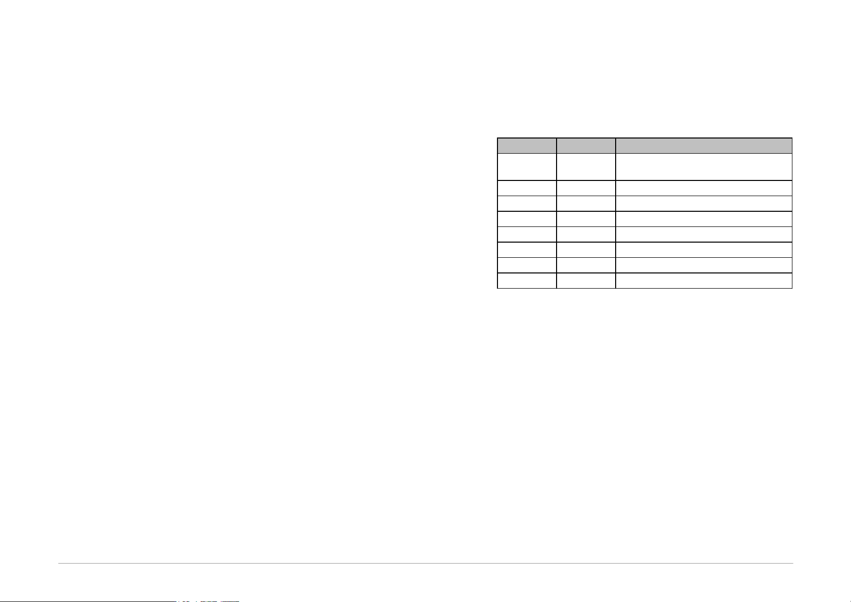
The following table describes the functions of PRESTO's
and FORTE's pins for programming by means of the JTAG
interface.
PRESTO
FORTE
Function
VPP
P
SCK (System Clock)/User defined state
during file execution and after.
-
-
Not connected pin (key)
VDD
VDD
Feeding of I/O buffers
GND
GND
Ground of I/O buffers
MOSI
D
JTAG TDI (Test Data In)
CLOCK
C
JTAG TCK (Test Clock)
MISO
I
JTAG TDO (Test Data out)
LVP
L
JTAG TMS (Test Machine State)
Table12: JTAG programming connector
8.2
Settings
This chapter explains the meaning of different settings in
Options ➙ Program Options.
8.2.1 Default TCK signal
frequency
This frequency of the TCK clock is used until the JTAG
Player reaches the first FREQUENCY command in the SVF
file or until the FREQUENCY with the "default" value is
reached.
The XSVF file format does not support the FREQUENCY
default command. Therefore frequency defined by
Default TCK Signal Frequency parameter is applied to
all operations.