presto_en.pdf - 第17页
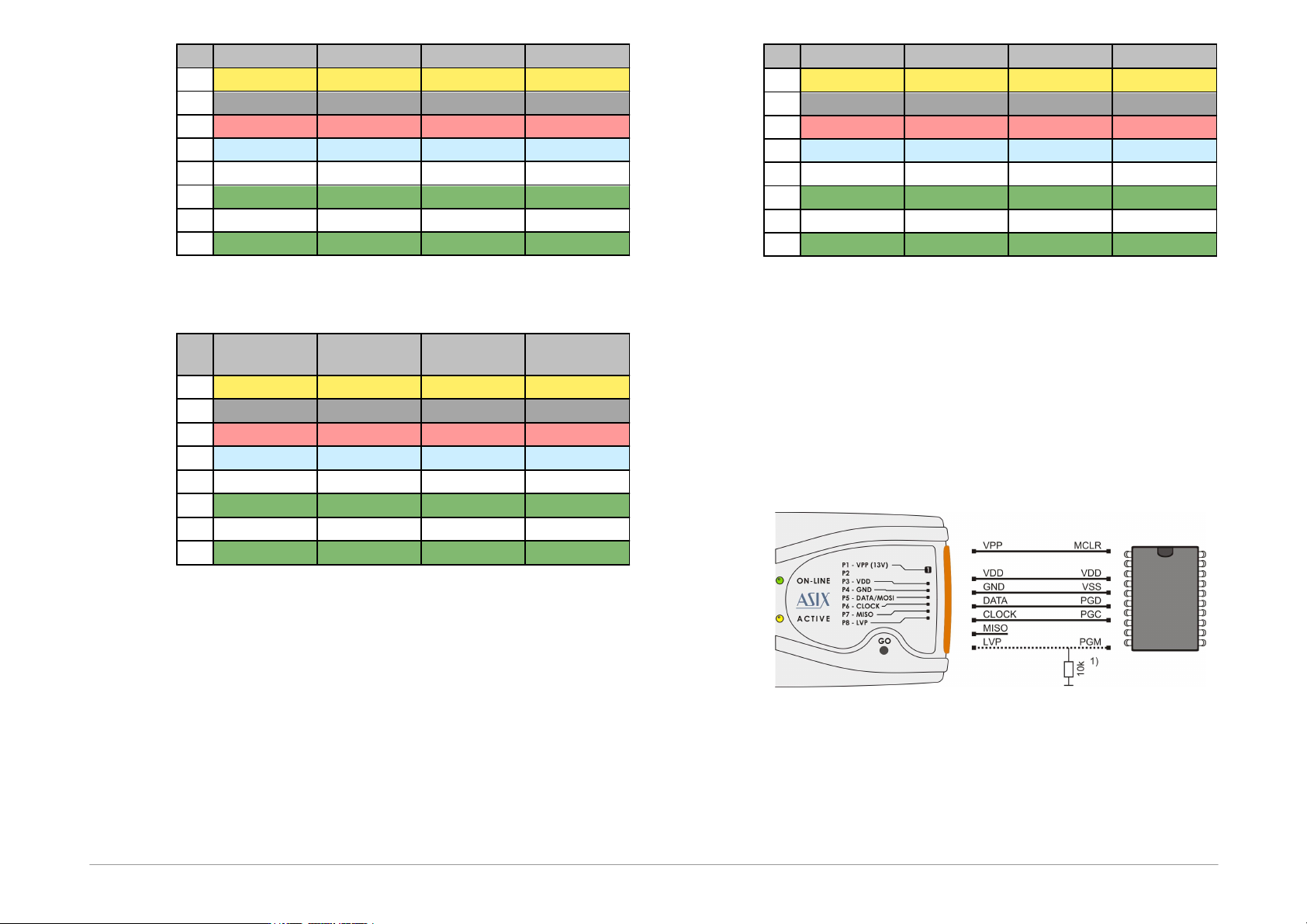
Page 17 P i n A V R A V R T P I 8 0 5 1 J T A G P 1 R E S E T R E S E T R E S E T U S R P 2 P 3 V C C V C C V C C V D D P 4 G N D G N D G N D G N D P 5 M O S I T P I D A T A M O S I T D I P 6 S C K T P I C L K S C K T C …
Page 16
FCI marking
Description
65039-036LF
housing, 1 pin
65039-029LF
housing, 1 x 8 pins
47217-000LF
pin
Table2: ICSP cable - material list
A cable with a cross-section between 0.1 and 0.3mm
2
may be used for making the custom connecting cable.
2.6.2 Programming in ZIF
Socket
If programming of autonomous device is required, i.e.
those that are only later connected to an application, it is
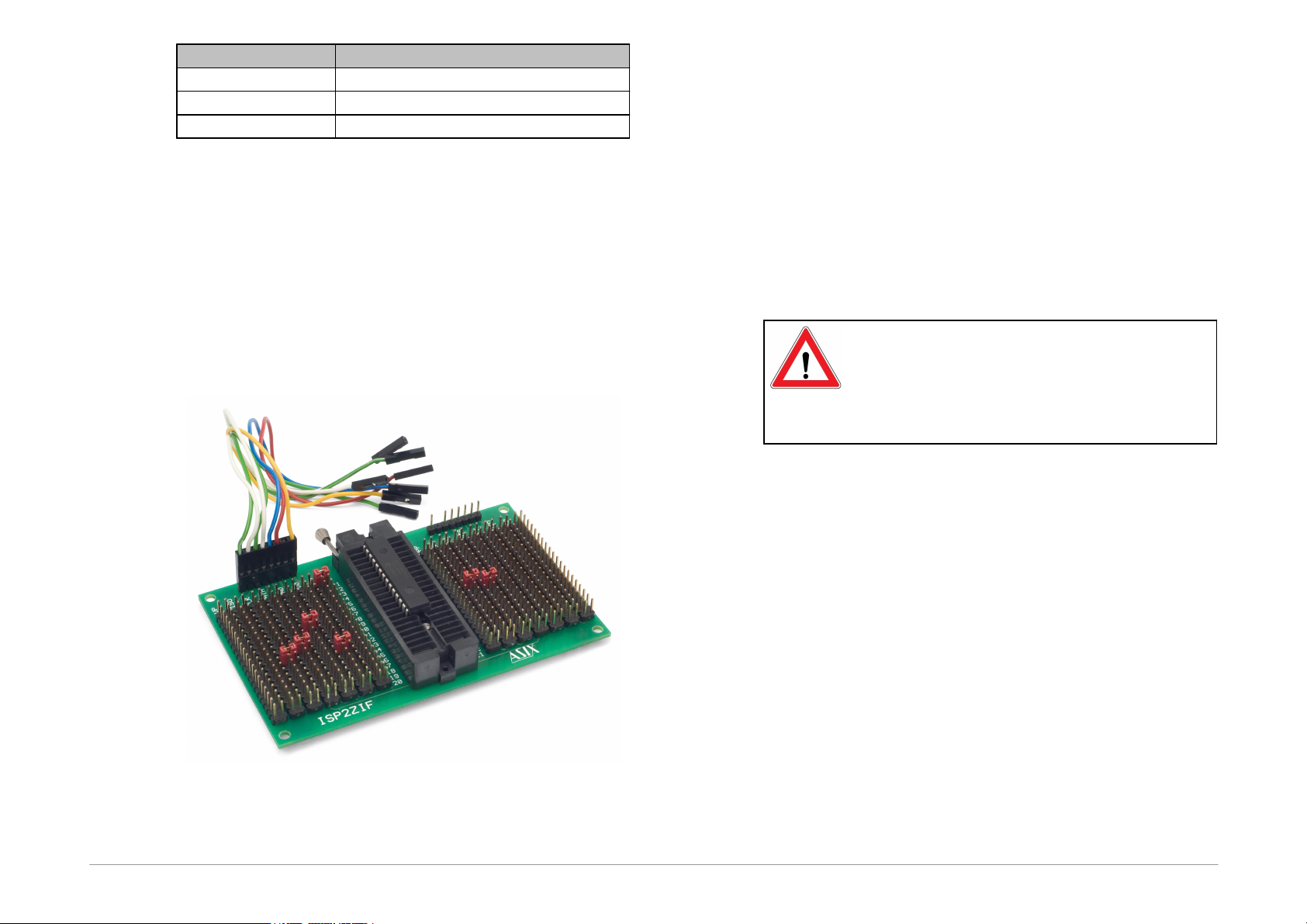
possible by means of our optional ISP2ZIF accessory.
Fig.5: ISP2ZIF
ISP2ZIF consists of a zero insertion force (=ZIF) socket
and an ICSP connector for connecting to the programmer,
which can also provide voltage for feeding the program
circuitry.
2.6.3 Connecting
Procedure
The correct procedure for connecting the programmer:
first connect PRESTO to the target application, then
connect PRESTO to the USB and finally turn on the
application’s power supply.
Please make sure that the GND of the application, the
programmer and the USB are interconnected before
signals and the power are applied.
Important warning
If an application is powered by a switched
power source or is not grounded, a significant
voltage difference may appear between the
programmer’s ground and the application’s
ground. This could damage the programmer.
The simplest way of connecting the GND prior to the
other signals is to ground the application before
connecting it to the programmer. This can, for example,
be achieved by making the GND pin of the application’s
ICSP connector longer than the other pins. It will make
sure that both grounds are interconnected first.
Page 17
Pin
AVR
AVR TPI
8051
JTAG
P1
RESET
RESET
RESET
USR
P2
P3
VCC
VCC
VCC
VDD
P4
GND
GND
GND
GND
P5
MOSI
TPIDATA
MOSI
TDI
P6
SCK
TPICLK
SCK
TCK
P7
MISO
MISO
TDO
P8
SS
TMS
Table3: Connection list No.1
Pin
PIC
MSP430
MSP430
SBW
TI CCxxxx
P1
MCLR
TEST
RESET
P2
P3
VDD
VCC
VCC
VDD
P4
VSS
VSS
VSS
GND
P5
PGD
TDI
SWBTDIO
Debug data
P6
PGC
TCK
SWBTCK
Debug clock
P7
TDO
P8
LVP
TMS
Table4: Connection list No.2
Pin
PSoC
I
2
C
SPI
Microwire
P1
XRST
CS
CS
P2
P3
VDD
VDD
VDD
VDD
P4
VSS
GND
GND
GND
P5
ISSP-data
SDA
SI
DI
P6
ISSP-SCLK
SCL
SCK
CLK
P7
SO
DO
P8
ORG(PRE)
Table5: Connection list No.3
2.6.4 Connection Examples
The following text presents examples of connections
between PRESTO and the device being programmed. We
use a notation according to the manufacturer datasheet
of each particular device.
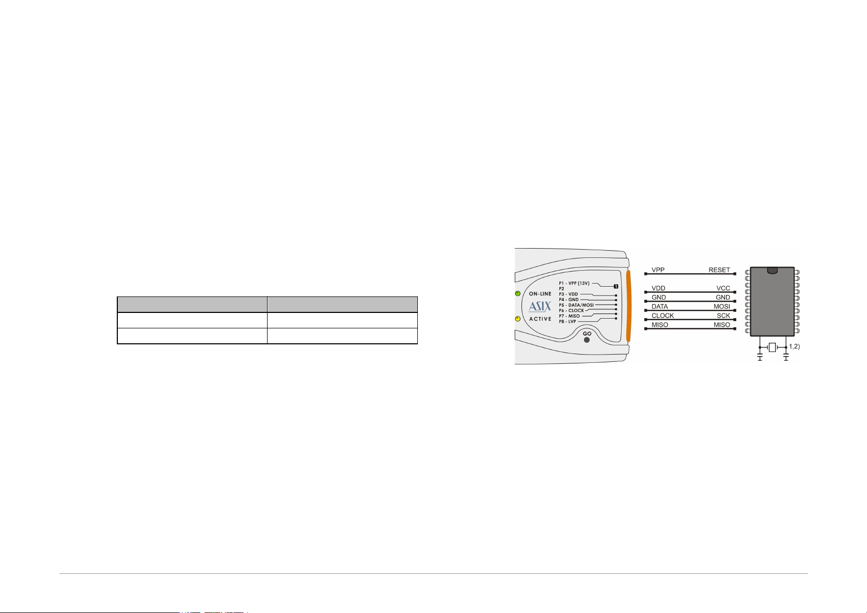
PIC Microcontrollers
Fig.6: PIC microcontroller
1) Not all PIC microcontrollers have the PGM pin. The
PGM pin can be connected to programmer’s L pin, to
VSS via a pull-down resistor (for HVP programming)
or to VDD via a pull-up resistor (for LVP
programming).
Page 18
2) The whole device must be erased before
programming if code/main memory protection (CP) or
data memory protection (CPD) is active.
3) Some PIC devices cannot be erased with CP or CPD
active being powered by voltage less than 5V.
4) If a microcontroller has more than one power-supply
VDD or VSS pin, all of them must be connected
including the AVDD and AVSS pins.
5) PIC microcontrollers which require 3V or lower power
supply must be fed from external power supply
because PRESTO can only provide 5V voltage.
6) Some PIC microcontrollers require voltage less than
13V on the MCLR pin while the programmer can only
set 13V voltage level on VPP. If such device has been
selected in UP, a warning message is displayed. It is
recommended to limit voltage on the MCLR pin by an
external circuit (a potential divider or a Zener diode
and a resistor).
VPP
Resistor
9V
390Ω
11V
200Ω
Table6: Recommended resistors values with Zener diode (the
value also depends on the rest circuit)
7) If the LVP mode is used, it is recommended to check
whether the LVP fuse is still set after erasing the part.
8) Programming of PIC32 devices is supported by
means of the ICSP interface only with external 3V
power supply.
9) Devices with an ICPORT fuse must have the
dedicated ICSP port off for LVP programming.
10) PIC24 and dsPIC33 devices may be programmed
using PE (Programming Executive) or using the
standard method. Programming by means of PE is
usually faster.
11) Programming of some new PIC microcontrollers in the
HVP mode can cause that a warning message
indicating overcurrent on VPP appears. If that
message does not indicate a real fault it could be
caused by different technology which has been used
by Microchip for producing new devices, although
they are from pristine families. These devices have
slightly different parameters. It could be solved by
connecting capacitor of 1nF between the VPP pin
and GND and resistor of 10Ω in serial with VPP signal
if the fault persists.
12) When the MCU debug mode is enabled using a fuse,
the programmer cannot communicate with it.
AVR Microcontrollers
Fig.7: AVR microcontroller
1) A source of the clock signal, which is set in the device
or which will be set by fuses during programming
must be connected to the device. A crystal must be
connected if set up as the clock source.
2) Device fuses have been set up by the producer to the
internal oscillator with a frequency of 1MHz. In the
initial programming, the device should be
programmed with “Oscillator frequency” set up at
“>750kHz” or lower in the “PRESTO programmer
settings” window.
3) Not all AVR microcontrollers allow use of a crystal
(e.g.ATtiny13, ATtiny15).