presto_en.pdf - 第35页
Page 35 want to save such a m odification, choose F ile ➙ Save, File ➙ Save as. .. or File ➙ Export data memory to file.... I m p o r t a n t w a r n i n g I t i s r e c o m m e n d e d t o c h e c k t h e p r o g r a m …
Page 34
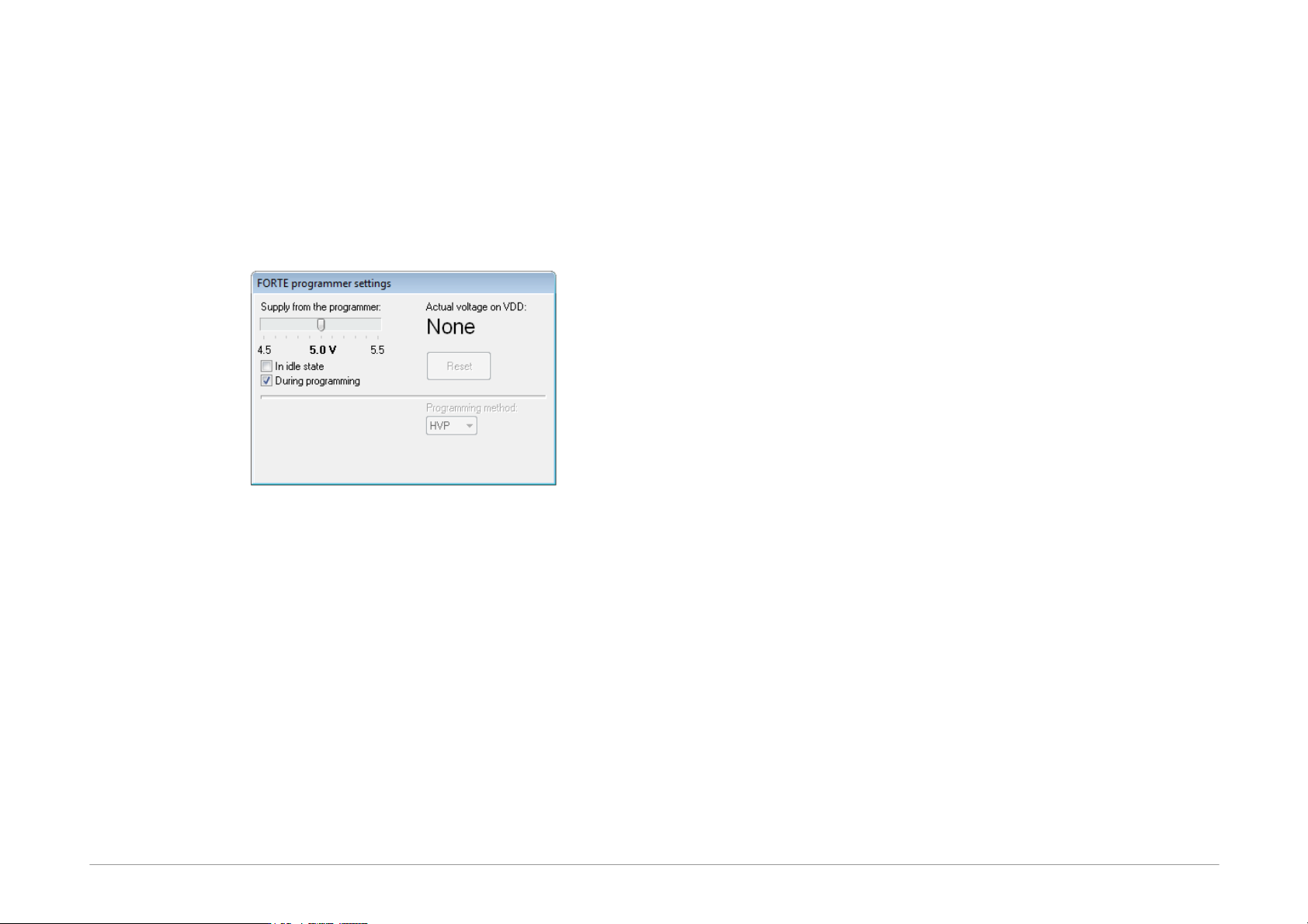
Programmer Settings
Each time a particular programmer is selected (FORTE or
PRESTO), the programmer settings window is displayed
allowing the user to set the voltage used and some other
important programming options.
If you are using an external power source for feeding the
application, the During programming option must not
be checked.
Fig.21: Programmer settings
The current voltage is continuously displayed in the top
right corner of this window.
Should an error i.e. overload occur, a warning appears at
this place.
The output voltage in the idle state if it is turn on can be
changed only if it is allowed under Options ➙ Program
settings ➙ Others ➙ Allow to change supply voltage
level when it is on (FORTE only).
If a voltage is present at the VDD pin, you can stop the
running microcontroller application by pressing the Reset
button and restart it by pressing the same button again.
Fuses and Working with Them
Characteristics of the device (fuse) to be programmed
can be set in the Configuration window. Changes in
fuses can be saved by choosing File ➙ Save or File ➙
Save project....
If the given .hex file of device includes definitions of its
fuses, fuses are saved in it.
Fuses are saved together with a project in the case of
Atmel microcontrollers and memory chips. If you are
working with these, right-click the Configuration window
once you have set the fuses and use the Learn fuses
option.
If the Options ➙ Program settings ➙ Programming ➙
Reload file before every programming option is
active, the software reloads current file after the
Program button is pressed. If, however, fuses are not
saved in current file and no project is created from which
fuses could be used, the configuration memory initializes
into the default state before each programming
procedure. This can be avoided by deactivating the
Program settings ➙ Files ➙ Erase configuration
memory before file reading option.
Many devices have specific requirements for fuse
settings. Further information on how to correctly set their
fuses can be found in the particular device data sheet.
5.3.5 Programming
Select the file that you want to program by choosing File
➙ Open....
Once the file opens, you can see the current code/main
memory, data memory and configuration memory (fuses).
If you cannot see these windows, activate them under
the View menu.
The memory being programmed can be manually
modified at any time by simply marking the required
location and rewriting its value from the keyboard. If you
Page 35
want to save such a modification, choose File ➙ Save,
File ➙ Save as... or File ➙ Export data memory to
file....
Important warning
It is recommended to check the programmer
settings and fuse settings before starting the
actual programming as an error in these
parameters could damage the device or even
the programmer.
The programming process is triggered by choosing
Device ➙ Program or by clicking the Program button.
In some devices, the system checks the Device ID (device
electronic signature) and the code/data protection bits
before launching the programming process. If the ID does
not match the selected device type, a warning message is
displayed.
Displaying of this warning message is frequently caused
by a fault in the interconnection of the device and the
programmer.
If things are in order, the programmer performs the
following operations: erases the device, checks the
erasure, programs the device and checks the
programmed device.
If only a particular memory of a microcontroller needs to
be programmed, it can be done by choosing the
corresponding item in the Device ➙ Program menu or
by clicking the pull-down arrow next to the Program
button on the button bar. Depending on the device type,
the following options may be available: program code/
main memory, program data (EEPROM) memory, program
configuration memory or program all.
Differential Programming
The Device ➙ Program menu offers a possibility of
differential programming, provided the device to be
programmed supports it. If selected, the existing memory
content is read first and only cells that differ are then
programmed.
Differential programming is useful for development during
which content of the programming data changes very
often, but the changes are tiny. As only changed cells are
overwritten, the differential programming is advisable for
devices with a low number of writing cycles. It can also be
faster than the conventional re-writing of the whole
memory content.
5.4
Further Features
The following section focuses on selected additional
functions of UP available for device programming.
5.4.1 Setting the GO
Button
ASIX programmers feature a GO button, which allows the
user to trigger the programming process without a
computer mouse or keyboard.
The function of the GO button can be set under the
Options ➙ Key shortcuts menu in the GO button field
to suit user's needs.
The UP software must be running if the user wants to use
the GO button, but may be minimized on the screen.
Additional settings associated with the GO button can be
found in
Settings for Programming During Development.
5.4.2 Mass Production
The mass production function is available under the
Device ➙ Program ➙ Mass production menu. It can
also be called up by clicking the arrow next to the
Program button on the toolbar.
Page 36
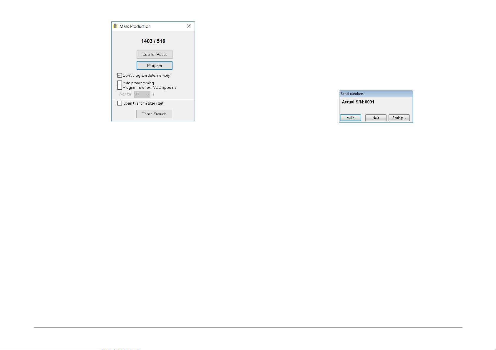
Fig.22: Mass production
The actual programming can be triggered by clicking the
Program button in the Mass production dialog
window.
The function of this button is identical to the Program all
or Program all except data memory options
depending on the state of the Don't program data
EEPROM checkbox in the Mass production window.
This dialog window also displays a counter of devices
programmed. Depending on the program settings, the
counter can also be displayed in the status bar. For
further information on settings see
Production
Programming Settings
.
The counter displays the number of programmed devices
in both the mass production mode and the standard
mode.
Pressing the Counter reset button zeroes all the mass
production counters. This operation cannot be undone.
The choice "Auto programming" causes that the device is
programmed after it has been connected, the connection
test is done by reading the Device ID.
The programming can be launched by connecting
external power supply (VDD).
When the "Open this form after start" setting is enabled,
the form opens after program start or after project file
open, if it is used.
5.4.3 Serial Numbers
The Serial Numbers function programs the serial number
or another sequence of characters in the selected
memory location.
Fig.23: Serial numbers
Once the serial numbers are activated and their type set
up under Options ➙ Program settings ➙ Serial
numbers, a window with the current serial number opens
offering the possibility to manually write a serial number
in the memory HEX editor, to specify where it should be
written and if the system should proceed to the next
sequential number.
Serial numbers can be:
• Computed
The computed serial numbers must always be written in
the same selected position in the device such as the
code/main memory, data memory or an ID position, for
example. The serial number is always expected to be a
number in decimal or hexadecimal format and may be
coded as a 4-bit combination (one to four characters per
word) or as an ASCII character (one or two ASCII
characters per word). If the code/main memory is used for
Microchip microcontrollers, you can choose RETLW
instructions. Then RETLW instructions are written in the
given address of the code/main memory together with a
parameter corresponding with the serial number.
• TakenfromFile
A single serial number can be distributed in more than