presto_en.pdf - 第94页
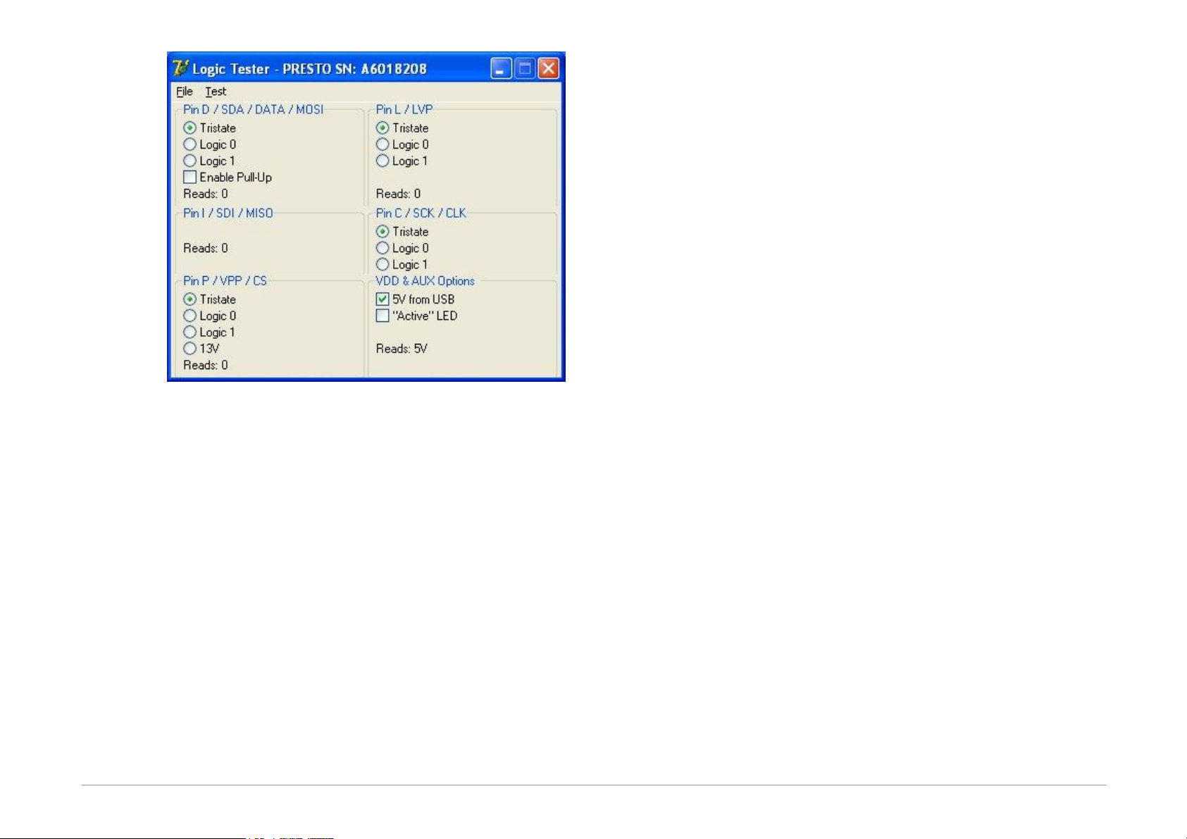
Page 94 Fig.27: Tester PRESTO After you start the tester, make sure that the programmer's out put b uffers are fed. You can eit her u se the 5 VfromUSB opt ion or connect an external power- supply voltage to t he…

Page 93
10
TROUBLE-SHOOTING
This chapter describes how to proceed if experiencing
difficulties with device programming. It also describes
testing utilities for PRESTO and FORTE programmers
designed to check if the programmer is in good condition
or damaged. Please go through all the tips and tricks
before you send your programmer to a service shop.
The testing utilities are not part of the UP software
installation, but they can be downloaded separately from
https://www.asix.tech/prg_testers_en.html.
10.1
Tips and Tricks
Should you experience difficulties with programming, we
recommend checking the following points:
• Check the microcontroller and programmer
connections according to the description in Connecting
to Application. Even though it may seem trivial, it is
recommended to check the connection twice and to
assume the second time that the link does not always
lead where you want it to or it leads to more than one
point.
• If a crystal or other auxiliary devices are used for
programming, (typically pull-down or pull-up resistors),
check if their values and connections are correct.
• It is advisable (and often necessary) to have blocking
capacitors at the power supply of the device to be
programmed.
• If the device to be programmed has more than one
power-supplying pin, all of them must be really fed. It
is often recommended to check their voltage with a
voltmeter.
• Use of the latest version of UP is recommended. If you
are still using an older version, an update is
recommended.
• Are you programming a new device or has it been
previously programmed? If so, the problems may be
caused by unsuitably set fuses in the device.
• The length of the ICSP cable should not exceed 15cm.
• Make sure that there is no additional capacity present
at the programming (data) pins. Consider if circuits on
the programming pins could cause too large a load for
programming.
• It is important that the crystal or the communication
speed settings reflect the reality in devices that need
that settings.
• Some devices may be programmed using several
different methods. Programming problems may be
caused by selecting a different programming interface
or a different programming mode than the ones that
the application is prepared for.
If none of the above tips help to eliminate the problem
and if it absolutely sure that the device to be
programmed is not faulty, the fault may lie in the
programmer.
To easily find out whether the programmer is in order or
not, you can use the testing utilities described in the
following chapters.
10.2
PRESTO Tester
he PRESTO Tester utility easily tests the “health
state” (usability) of the PRESTO programmer right at the
customer's site.
In order to run it successfully, only one PRESTO
programmer may be connected to the control PC and its
drivers must be correctly installed. This is confirmed by
the green LED being on.
Page 94
Fig.27: Tester PRESTO
After you start the tester, make sure that the
programmer's output buffers are fed. You can either use
the 5VfromUSB option or connect an external power-
supply voltage to the VDD pin. The level of detected
voltage is displayed in the lower part of the VDD&AUX
panel.
Basic communication with the programmer can easily be
recognized by the Active diode being on. You can also
use the Test ➙ USB Flood Test menu option, which
tests the USB communication with the programmer in
both directions.
The programmer's serial number is displayed in the
window title bar. This number is necessary for any
communication with the service shop. You can also find
this number on the bar code label attached to the
programmer bottom.
Now you can switch logical levels for individual output
pins (pins P, D, D and L) and check the output signal
quality using a voltmeter. At the same time, the input
pins (pins P, D, I and L) indicate what logical level is
currently seen by the programmer.
In addition, a pull-up resistor may be connected to pin D.
This means that if its output is in the Tristate mode, pin D
starts reading log.1.
The programming voltage of 13V can be connected to
the output of pin P.
If everything seems to be in order, but the device still fails
to get programmed, it is recommended to check the
application connection according to instructions for
connecting a microcontroller to the programmer.
If in doubt as to whether the programmer is in order or
faulty, do not hesitate to contact our technical support.
Page 95
11
HPR3V3
HPR3V3 is an optional accessory to the PRESTO
programmer for programming of stand-alone 3.3V
devices as for example DataFlash Memories. The PRESTO
programmer can supply a programmed device with 5V.
However, some devices require 3.3V supply voltage and
3.3V logic levels on their pins. In such case, the HPR3V3
level shifter or an external 3.3V power supply have to be
used.
11.1
Usage
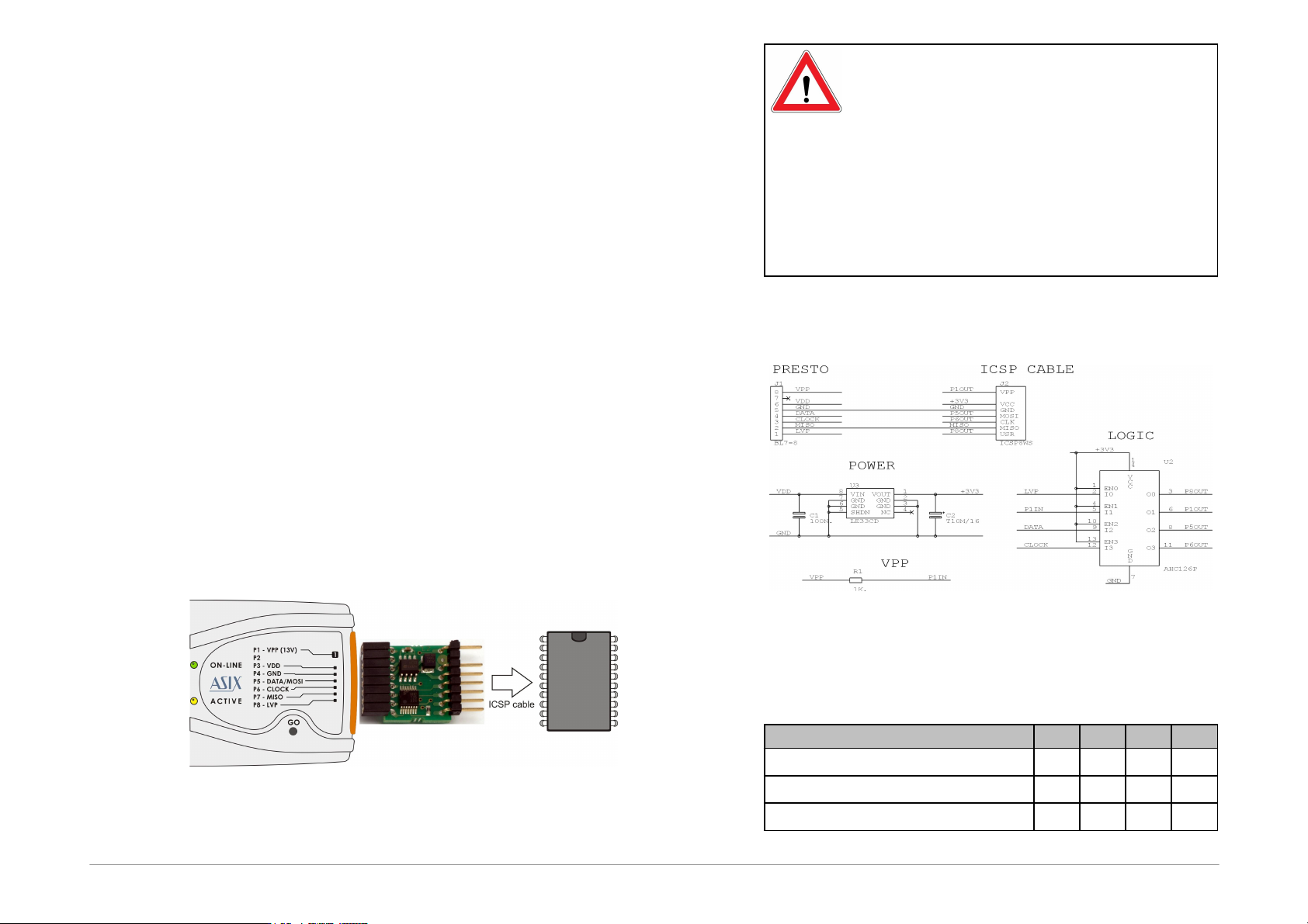
Plug the HPR3V3 level shifter directly to the pins of the
PRESTO programmer (NOT to the programmed device
connector!). Pin 2 is used as a key, so that it is not
possible to connect it wrong way. Now, connect the
programmed device to HPR3V3 using ICSP cable.
Connection of the programmed device pins is the same as
connection of the device to PRESTO.
Common connection diagram is below.
Fig.28: Use of HPR3V3
Set internal power supply for programming.
Important warnings
The HPR3V3 pins are unidirectional, so this
level shifter can be used for devices with
unidirection signals like SPI Flash memories,
AVR devices or MSP430 devices without SBW
interface, but it cannot be used for PIC
devices or MSP430 devices with SBW
interface.
Never connect an external voltage to the
output 3.3V supply pins!
11.2
HPR3V3 schematics
Fig.29: HPR3V3 schematics
11.3
Technical specification
min.
typ.
max.
V
CC
output supply voltage
3.2
3.3
3.37
V
I
CC
output supply current
90
mA
V
OH
output pin voltage log.1
2.9
V