Utah-94-721002-System-Manual.pdf - 第137页
System Manual lñÑçêÇ=fåëíêìãÉåíë=mä~ëã~ =qÉÅÜåçäçÖó== mä~ëã~ä~Ä póëíÉãNMM WARNING BEFORE PROCEEDING WITH ANY MAINTENANCE WORK, READ SECTION 1 - HEALTH AND SAFETY . j) If it should become necessa ry to change from PFPE to…

mä~ëã~ä~ÄpóëíÉãNMM lñÑçêÇ=fåëíêìãÉåíë=mä~ëã~=qÉÅÜåçäçÖó== System Manual
WARNING
BEFORE PROCEEDING WITH ANY MAINTENANCE WORK, READ SECTION 1 - HEALTH AND SAFETY.
SKNN= mìãé=äìÄêáÅ~åíë=
CAUTION
When changing or topping-up the lubricating oil in a pump, always use oil of the
same brand and type. If a change of brand or type is contemplated, refer to
Oxford Instruments Plasma Technology for advice.
SKNNKN= dÉåÉê~ä=
The lubricating oils used for pumps where the oil comes into contact with the pumped gases,
i.e. oil-sealed pumps such as rotary vane types, should be chosen to meet the specific
characteristics necessary for the process involved.
The vapour pressure must be low at the temperatures reached at the rubbing surfaces.
Viscosity should not vary significantly over the temperature range involved, and the water
absorption rate and content must be low.
Lubricating oils generally fall into one of two categories: mineral (hydrocarbon) based oil or
synthetic oil such as perfluorinated polyether. The synthetic oils are normally used where they
come into contact with strong oxidants such as nitrogen dioxide, oxygen, or one of the
halogens.
SKNNKO= mÉêÑäìçêáëÉÇ=éçäóÉíÜÉêë=
Perfluorised polyether (PFPE) lubricants have the following properties:
a) They are stable up to 350
o
C, i.e. they do not decompose below this temperature.
b) They are chemically inert. They will, however, react with Lewis acids (BCl
3
, AlCl
3
etc.)
at temperatures over 100
o
C.
c) They do not polymerise under the impact of high-energy radiation.
d) Since they tend not to keep contaminants suspended, pumps using these lubricants
must always be fitted with suitable oil filters.
e) They do not 'age' and therefore, if used correctly, need not be replaced during the
lifetime of the pump.
f) Any contaminants in the lubricant may be removed by fitting clean filters and
letting the pump run for several hours with inert gas ballast, the intake port having
been closed.
g) They do not protect metal surfaces against corrosion. Pumps should therefore always
be flushed with inert gas. Pumps using PFPE should be allowed to run continuously.
h) PFPE is incompatible with hydrocarbon oils, i.e. mineral oils, conventional greases
and cleaning agents.
i) If a pump uses PFPE lubricant only Freon 113 or Frigen 113 may be used as a cleaning
agent, and only PFPE grease may be employed.
Maintenance
UC Davis 94-721001 Issue 1: March 06 Page 6-18 of 22 Printed: 22-Mar-06, 7:41

System Manual lñÑçêÇ=fåëíêìãÉåíë=mä~ëã~=qÉÅÜåçäçÖó== mä~ëã~ä~ÄpóëíÉãNMM
WARNING
BEFORE PROCEEDING WITH ANY MAINTENANCE WORK, READ SECTION 1 - HEALTH AND SAFETY.
j) If it should become necessary to change from PFPE to mineral oil lubrication or vice
versa, the pump must be completely disassembled, freed of lubricant and fitted with
new gaskets and vanes.
k) At temperatures over 350
o
C, hazardous gaseous decomposition products are
formed. Therefore do not smoke in rooms where PFPE is used, and make sure that
no tobacco comes into contact with PFPE.
l) When handling PFPE, protective clothing must be used.
m) Do not mix PFPE with used oil. Dispose of them separately.
n) PFPE is normally odourless and colourless. Cloudiness or odour is a sign of
contamination.
SKNNKP= eóÇêçÅ~êÄçå=äìÄêáÅ~åíë=
Where mineral oils are used, the rate of oil deterioration for a particular pump and process
should be established at an early stage, and oil changes based upon this information.
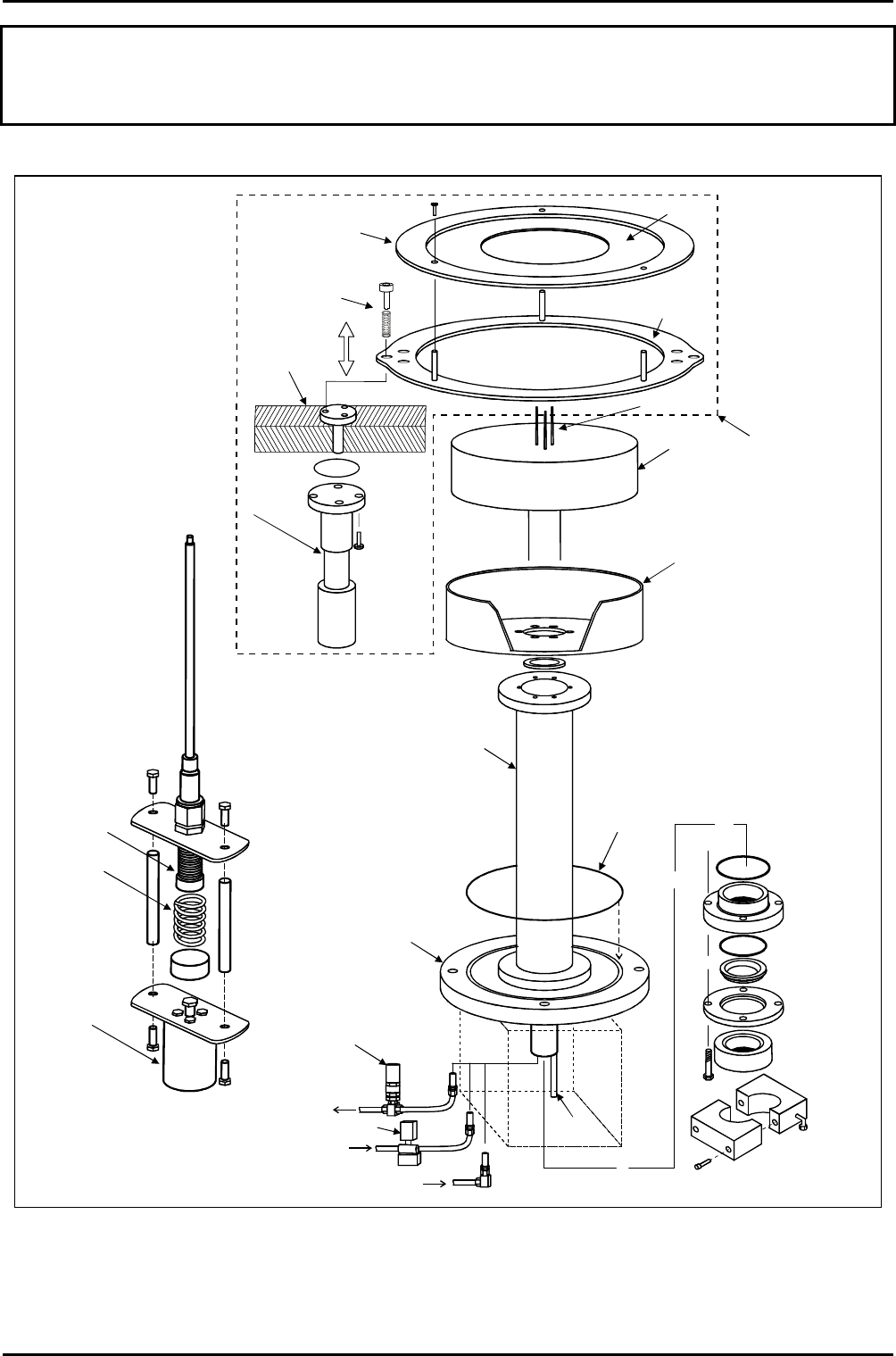
SKNO= VQJNMMJRJNO^=`êóç=L=ÜÉ~íÉÇ=JNRM=L=QMM`=eÉ=äçïÉê=ÉäÉÅíêçÇÉ=
ï~ÑÉê=Åä~ãéáåÖ=éä~íÉ=ÅÜ~åÖÉçîÉê=éêçÅÉÇìêÉ=
Before carrying out a process, in the process chamber on a wafer which is a different size to
that last processed, it is necessary to fit the correct type of clamping plate. Clamping plates
are available for various sized wafers.
To change the clamping plate, use the following procedure (refer to Fig 6.1, page 6-20):
6) If necessary, vent the process chamber.
7) Open the process chamber lid.
8) Wearing powder-free gloves, unscrew the three clamping plate securing screws then
remove the clamping plate from the process chamber and place on a clean surface.
9) Take the replacement clamping plate and mount it on the three supporting pillars
then insert and tighten the three securing screws.
10) Close the process chamber lid.
Maintenance
Printed: 22-Mar-06, 7:41 Page 6-19 of 22 UC Davis 94-721001 Issue 1: March 06
mä~ëã~ä~ÄpóëíÉãNMM lñÑçêÇ=fåëíêìãÉåíë=mä~ëã~=qÉÅÜåçäçÖó== System Manual
WARNING
BEFORE PROCEEDING WITH ANY MAINTENANCE WORK, READ SECTION 1 - HEALTH AND SAFETY.
THERMOCOUPLE
CHAMBER
BASE
WAFER
CLAMP
TABLE
DARK SPACE
SHIELD
TABLE SUPPORT
TUBE
O RING
PUMPDOWN
PIPE FLANGE
FEEDTHROUGH
COMPONENTS
STAINLESS
STEEL
BELLOWS
SPRING
COMPRESSED
AIR CYLINDER
COMPRESSED
AIR CYLINDER
(ONE EACH SIDE
OF CLAMPING
PLATE)
WAFER
LIFT
ASSEMBLY
(FITS INSIDE
TABLE SUPPORT
TUBE)
Clamping
plate
Clamping
ring
Setscrew &
compression
spring (3-off
on each side
of clamping
ring)
3-pin wafer
support
Quartz
insert
SAFETY RELIEF
VALVE
CONTROL VALVE
LIQUID NITROGEN
IN
LIQUID NITROGEN
OUT
HELIUM IN
Fig 6.1: 94-100-5-12A Cryo / heated -150 / 400C He lower electrode
Maintenance
UC Davis 94-721001 Issue 1: March 06 Page 6-20 of 22 Printed: 22-Mar-06, 7:41