Utah-94-721002-System-Manual.pdf - 第210页
mä~ëã~ä~Ä póëíÉãNMM = lñÑçêÇ=fåëíêìãÉåíë=mä~ëã~=qÉÅÜåçäçÖó Installation Data RK= pÉêîáÅÉë= The required services are li sted in the following sub-sections. For full details of services specifications including connection…
Installation Data= lñÑçêÇ=fåëíêìãÉåíë=mä~ëã~=qÉÅÜåçäçÖó mä~ëã~ä~ÄpóëíÉãNMM
646
1286
200
100
100 mm DIAMETER
EXTRACTION COLLAR
EARTH (GROUND)
TERMINAL BLOCK
316
386
456
526
596
666
736
806
876
946
1016
1086
1156
1226
0
ENTRY GLANDS FOR
COMPRESSED AIR PIPE
AND ELECTRICAL CABLES
(CONTROL CABLE TO MAIN
UNIT IS 3 METRES LONG)
¼"
160
30
SECONDARY GAS OUTLET
LINE TO SYSTEM (ONLY
USED IF A SPLIT MANIFOLD
IS FITTED)
PRIMARY GAS
OUTLET LINE TO
SYSTEM
GAS INLET
LINES
ALL INLET GAS
LINES ARE ¼"
STAINLESS STEEL
TUBE FOR WELDING
TO THE CUSTOMER'S
SUPPLY.
NOTES:
20
20
20
623
1246
LOCATION OF FIXING HOLES,
EACH 6.6 mm DIAMETER
606
CLEAN GAS LINE
CAN BE MFC
CONTROLLED
(THIS WILL OCCUPY
ONE GAS LINE
POSITION)
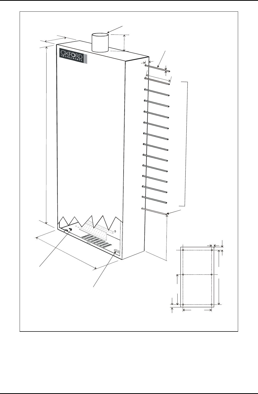
Fig 8: 12-line gas pod
Installation Data (ICP 180)
Printed: 22-Mar-06, 6:57 Page 13 of 18 Issue 5: June 05

mä~ëã~ä~ÄpóëíÉãNMM= lñÑçêÇ=fåëíêìãÉåíë=mä~ëã~=qÉÅÜåçäçÖó Installation Data
RK= pÉêîáÅÉë=
The required services are listed in the following sub-sections. For full details of services
specifications including connection diagrams, electrical connection schematic etc., read in
conjunction with the Oxford Instruments Plasma Technology ‘Services Specifications for
Plasmalab and Ionfab Systems’ document.
RKN= bäÉÅíêáÅ~ä=pìééäó=êÉèìáêÉãÉåí=
Function Connection Parameter Specification
Voltage 208Vac ±10%
Current 50 A
Frequency 50 / 60 Hz
System electrical
supply (208V
system)
Cable (4 meters
long)
Phases 3 phase, N + E
Voltage 380Vac –10% to 415Vac
+6%
Current 50 A
Frequency 50 / 60 Hz
System electrical
supply (415V
system)
Cable (4 meters
long)
Phases 3 phase, N + E
RKO= t~íÉê=`ççäáåÖ=êÉèìáêÉãÉåí=
Function Connection Parameter Specification
Flow 1 lpm (0.27 gpm (US)) Process turbo
1
/
4
” stainless steel
Swagelok
Temperature 15 - 25°C (59 - 77°F)
Flow 8 lpm (2.12 gpm (US)) RF Generator and
ICP
3
/8” stainless steel
Swagelok
Temperature 10 - 25°C (50 - 77°F)
Flow 2 lpm (0.53 gpm (US)) ICP & AMU
3
/8” stainless steel
Swagelok
Temperature 10 - 25°C (50 - 77°F)
Flow 1 lpm (0.27 gpm (US)) Load lock turbo (if
required)
1
/
4
” stainless steel
Swagelok
Temperature 15 - 25°C (59 - 77°F)
RKP= içïÉê=bäÉÅíêçÇÉ=`ççäáåÖ=êÉèìáêÉãÉåí=
Function Connection Parameter Specification
Flow 2 lpm (0.53 gpm (US)) Liquid cooled lower
electrode
3
/8” stainless steel
Swagelok to heater /
chiller unit
Temperature As required by process
LN2 Cryo cooled
lower electrode
¼” stainless steel
Swagelok to dewar
Flow As required by process
RKQ= `çãéêÉëëÉÇ=^áê=êÉèìáêÉãÉåí=
Function Connection Parameter Specification
Flow 5 lpm (0.2 cfm)
(combined with gas
pod)
System CDA 4mm push-fit Legris
Pressure 4.0 – 6.0 Bar (60 – 90
psi)
Flow 5 lpm (0.2 cfm)
(combined with system)
Gas pod CDA 4mm push-fit Legris
Pressure 4.0 – 6.0 Bar (60 – 90
psi)
Installation Data (ICP 180)
Issue 5: June 05 Page 14 of 18 Printed: 22-Mar-06, 6:57

Installation Data= lñÑçêÇ=fåëíêìãÉåíë=mä~ëã~=qÉÅÜåçäçÖó mä~ëã~ä~ÄpóëíÉãNMM
RKR= káíêçÖÉå=êÉèìáêÉãÉåí=
Function Connection Parameter Specification
Flow 10 lpm (0.4 cfm) System N
2
¼” stainless steel
Swagelok
Pressure 3.0 Bar (45 psi)
minimum
Flow Refer to sub-section 6.1
Rotary pump purging
Rotary pump purge ¼” stainless steel
Swagelok typically
Pressure Refer to
sub-section 6.1
Rotary pump purging
RKS= mêçÅÉëë=Ö~ë=êÉèìáêÉãÉåí=
Function Connection Parameter Specification
Process gas in ¼” stainless steel
welded pipe at gas
pod, ¼” stainless
steel VCR at system.
Pressure 2.0 – 3.0 Bar (30 – 45
psi)
RKT= eÉäáìã=êÉèìáêÉãÉåí=
Function Connection Parameter Specification
Helium in ¼” stainless steel
Swagelok
Pressure 2.0 – 3.0 Bar (30 – 45 psi)
RKU= bñíê~Åíáçå=êÉèìáêÉãÉåí=
Function Connection Parameter Specification
ICP180 100mm (4”) tube Flow 1 m
3
/hour (0.6 cfm)
Gas pod 100mm (4”) tube Flow 6-line gas pod – 1
m
3
/hour (0.6 cfm)
12-line gas pod – 3
m
3
/hour (1.8 cfm)
Rotary pump
exhaust
Refer to Section 6
Pump set
information
Installation Data (ICP 180)
Printed: 22-Mar-06, 6:57 Page 15 of 18 Issue 5: June 05