Utah-94-721002-System-Manual.pdf - 第276页
^ää=lfmq=póëíÉãë l ñÑçêÇ =fåëíê ìãÉåíë =m ä~ëã~=q ÉÅÜåçäçÖó== System Manual System Type Set C1 to Then move in Drive C1 Motor to Set C2 to Then Move in Drive C2 Motor to RIE/DP Maximum 1 turn Maximum (999) Maximum 1 turn…

System Manual lñÑçêÇ=fåëíêìãÉåíë=mä~ëã~=qÉÅÜåçäçÖó== ^ää=lfmq=póëíÉãë
PKO= mêçÅÉÇìêÉ=
WARNING
HAZARDOUS RF VOLTAGE - CONTACT CAN CAUSE DEATH, SEVERE INJURY
OR BURNS.
ENSURE THAT THE RF SUPPLY IS SWITCHED OFF WHILE CARRYING OUT
STEPS 1 TO 8.
1) Connect the AMU to the system. Make a good earth bond between the vacuum
chamber and the AMU chassis.
2) Connect the output strap to the plasma electrode with at least a 25 mm wide copper
strap, with at least 10 mm clearance between the live strap and any earthed part.
3) Confirm the polarity and voltage of the dc power source before connecting to the
Sense and Control PCB:
JP7 pin 1 +24 Vdc
JP7 pin 2 0 V
4) Ensure the ventilation fans are all pulling air
out of the automatch case and check
the system cooling is turned on. For sense board cooling, check one fan is pulling air
out and one is pulling air in to the sense board section.
5) Confirm the operation of each motor using the manual drive. An increase in
capacitor position should make the vanes overlap more. In the case of a vacuum
capacitor, an increase in position should turn the capacitor shaft anti-clockwise,
when looking at it from the motor end (see Fig 5). Check with a capacitance meter in
case of doubt.
If the motors do not turn in the correct direction check the plug in connector on the
board, refer to OIPT Work Instruction No. 39.
6a) Calibrate the motors and their respective positions as follows:
For gear driven capacitors: Loosen screws retaining the motors to the AMU box,
but don’t remove completely and ensure the gears don’t mesh.
For direct drive capacitors: Unscrew the motor plate attached to the side of the
AMU box and pull the coupling apart.
Then,
For Air Vane Capacitor AMU:
Keeping gears separated, overlap the vanes fully. Then, making sure that the gears
don’t mesh, drive both motors to maximum (999), using the AMU control panel.
For Vacuum Capacitor AMU (AMU board REV05 and earlier):
Set the capacitor positions and drive motors to their required position according to
the system type as shown in the following table:
OIPT Automatch Unit
Printed: 5-Jan-06, 8:03 Page 9 of 20 Issue 6: February 05
^ää=lfmq=póëíÉãë lñÑçêÇ=fåëíêìãÉåíë=mä~ëã~=qÉÅÜåçäçÖó== System Manual
System
Type
Set C1
to
Then
move
in
Drive
C1
Motor
to
Set C2
to
Then
Move
in
Drive
C2
Motor
to
RIE/DP
Maximum
1 turn
Maximum
(999)
Maximum
1 turn
Maximum
(999)
ICP180
Maximum
1 turn
Maximum
(999)
Minimum
1 turn
Minimum
(000)
Ion Beam
Minimum
1 turn
Minimum
(000)
Minimum
1 turn
Minimum
(000)
ICP 380
Maximum
1 turn
Maximum
(999)
Maximum
7 Turns
Maximum
(999)
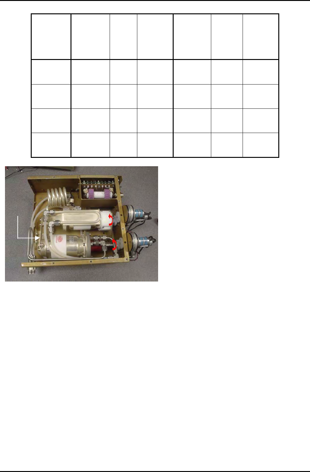
Padding
capacitor
mounting
position
Fig 5: Capacitor shafts rotation direction
To find the minimum position, turn the capacitor
shaft in the direction of the arrow, shown in Fig
5.
To find the maximum position, turn the
capacitor shaft opposite to the direction of the
arrow in Fig 5.
At the minimum position, the shaft becomes
stiff; at the maximum position, the shaft
becomes loose. Do not try to turn the shaft
past these points. If when turning the
capacitor to the maximum position, the shaft
becomes loose, turn the shaft back in until it just
begins to bite, this is the maximum position.
For Vacuum Capacitor AMU (AMU board with capacitor range mod.):
(Applies to all system types) Rotate the vacuum capacitor shaft clockwise as you
look at it from the motor end (see Fig 5) until the shaft just becomes stiff, and then
turn in half a turn. Making sure the motors don’t mesh, drive both motors to
minimum (000).
6b) For gear driven capacitors: Re-mesh the gears and tighten motor retaining
screws, ensuring that the motor and capacitor positions don’t move.
For direct drive capacitors: Loosen the coupling clamp screw on the capacitor
side, turn the coupling on the capacitor side until it lines up wit that on the motor
side ensuring neither the capacitor nor the motor change position at any time. Clip
the coupling together and tighten the clamp screw. Then re-attach the motor plate.
7) Confirm the ‘end of range’ stop functions using the manual drive switches located
on the AMU panel:
Drive C1 positive to the stop position; LED 101 lights; stop point in the range 950-999
OIPT Automatch Unit
Issue 6: February 05 Page 10 of 20 Printed: 5-Jan-06, 8:03
System Manual lñÑçêÇ=fåëíêìãÉåíë=mä~ëã~=qÉÅÜåçäçÖó== ^ää=lfmq=póëíÉãë
Drive C1 negative to the stop position; LED 102 lights; stop point in the range 000 -
050
Drive C2 positive to the stop position; LED 1 lights; stop point in the range 950-999
Drive C2 negative to the stop position; LED 2 lights; stop point in the range 000 - 050
If these aren’t working as stated, refer to section 5 or OIPT Work Instruction No. 39
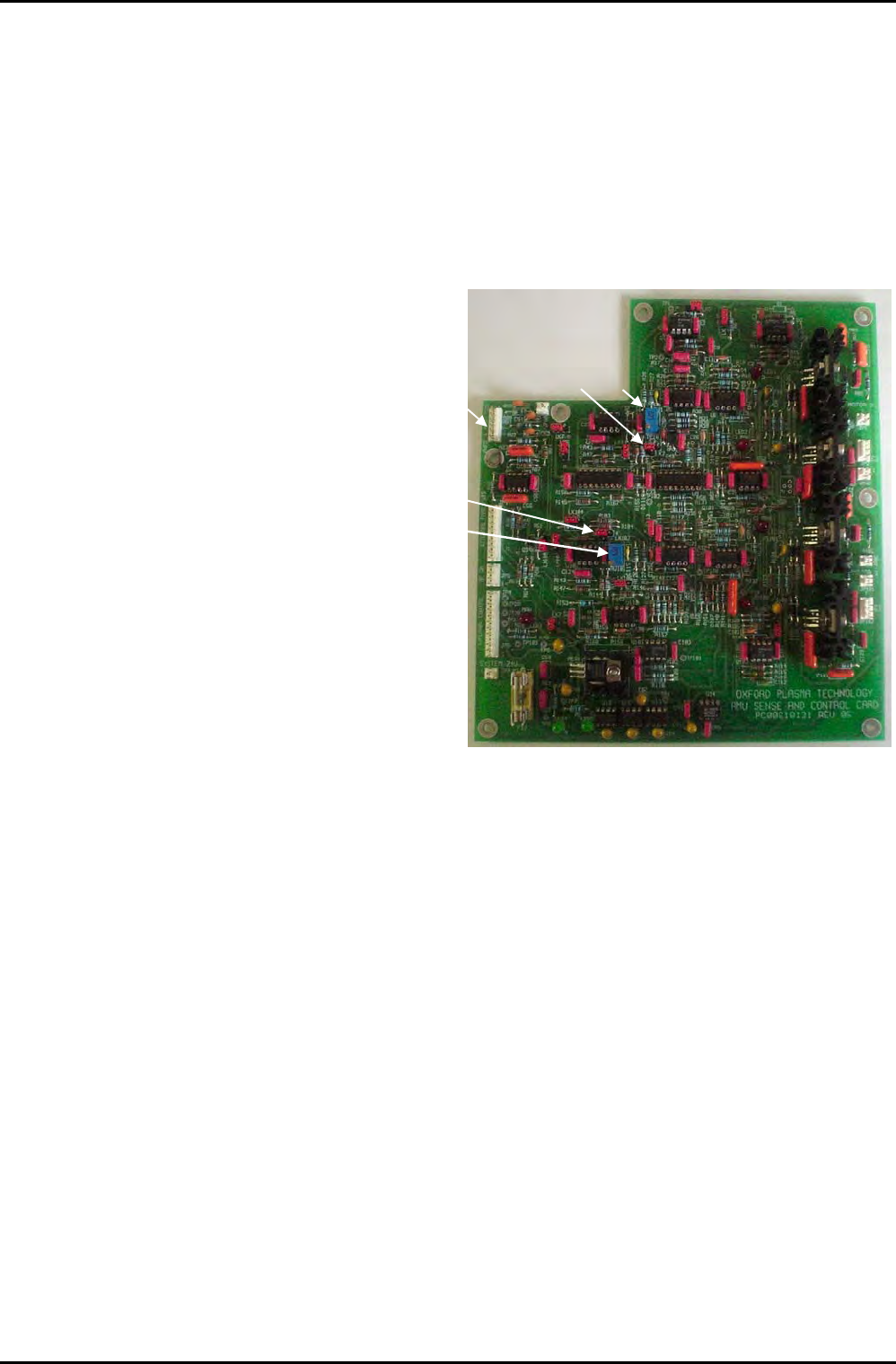
8) Set LK2 and LK 102 to
position ‘b’, and then
turn RV1 and RV101 fully
clockwise until they
begin to click (see Fig 6
or Fig 4).
RV1LK2
JP3
LK102
RV101
Fig 6: Component locations
9) Fit all covers to the AMU ensuring that they are securely fitted and connect the RF
generator to the matching unit. Evacuate the process chamber and turn on a low
power process.
For a Plasmalab system, a suitable process would be:
RF Generator output: 50 W
Pressure: 50 mTorr (RIE), 1 Torr (PECVD), 0.1 Torr (PE)
Gas: 20-100 sccm air, nitrogen or argon.
For an ion beam system, a suitable process would be:
RF generator output: 150 W (3 cm to 5 cm diameter)
300 W (15 cm to 20 cm diameter)
Gas: 10 sccm Argon
It may be necessary to use a gas burst to start the plasma, and it may be
necessary to start the neutralizer, if fitted.
OIPT Automatch Unit
Printed: 5-Jan-06, 8:03 Page 11 of 20 Issue 6: February 05