Utah-94-721002-System-Manual.pdf - 第292页
mä~ëã~ä~Ä póëíÉã=NMM Ef`m=NUMF= lñÑçêÇ=fåëíêìãÉåíë=mä~ëã~=qÉÅÜåçäçÖó= Illustrated Parts Catalogue Issue 2: November 02 Page vi of vi Printed: 16-Jan-06, 15:55 Interface PCB (inside door) (see Sub-section 0.3) REAR VIEW P…
mä~ëã~ä~Ä póëíÉã=NMM lñÑçêÇ=fåëíêìãÉåíë=mä~ëã~=qÉÅÜåçäçÖó=
Illustrated Parts Catalogue
Ef`m=NUMF=
Issue 2: November 02
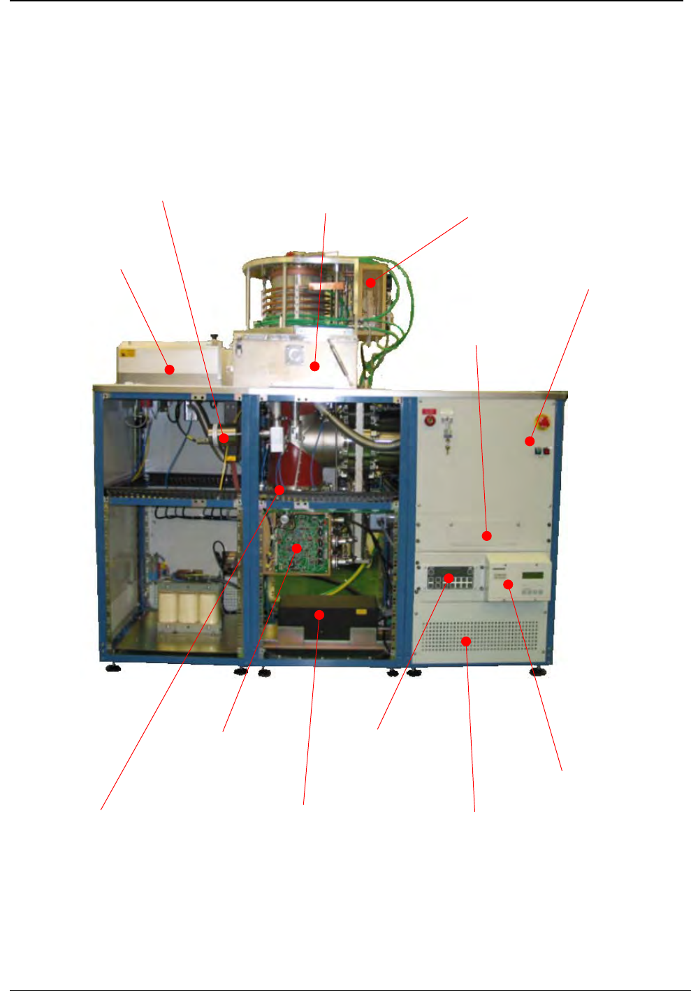
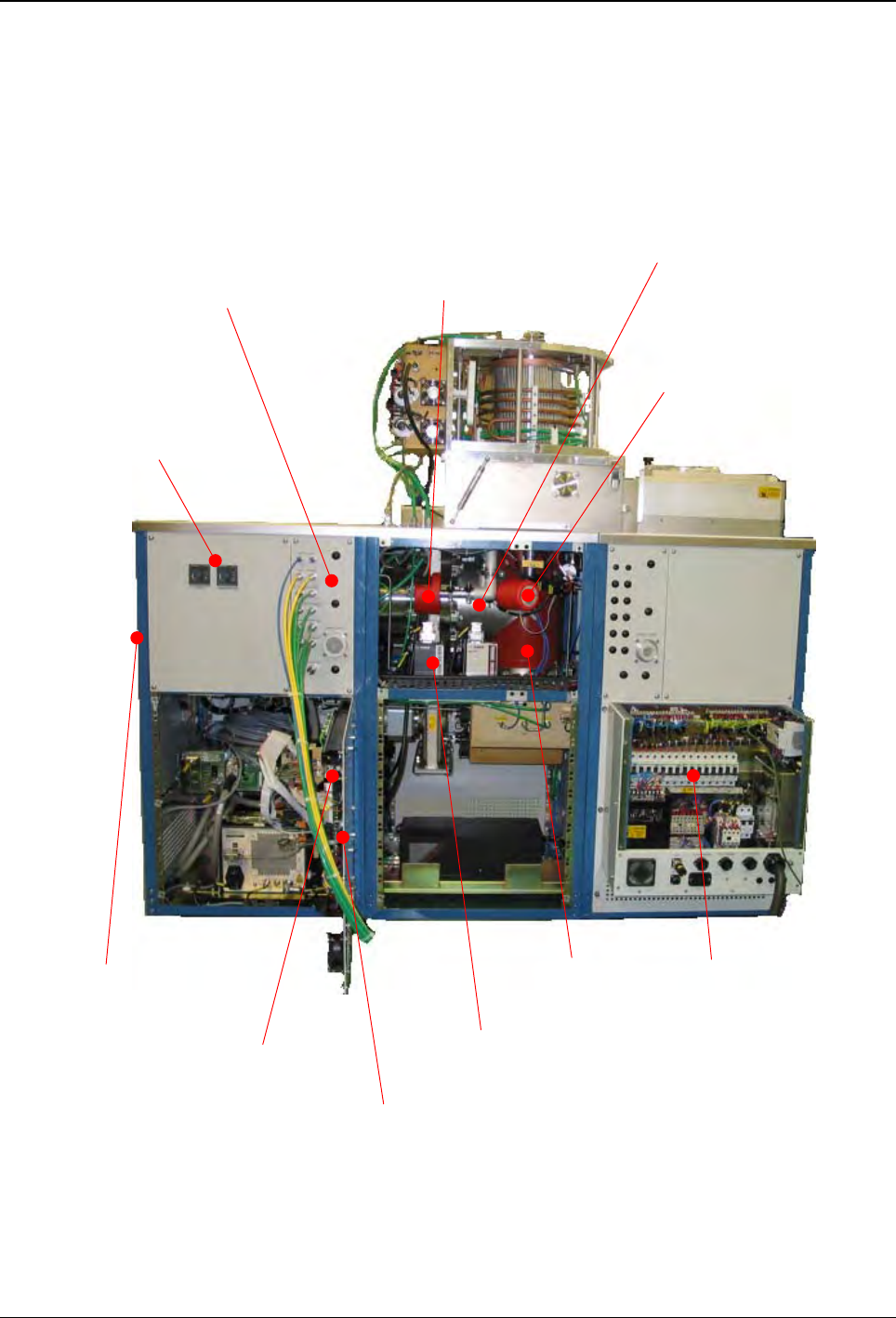
içÅ~íáçå=çÑ=ã~àçê=ÅçãéçåÉåíë=
FRONT VIEW
Capacitance manomete
r
(see Section 7)
Process Chambe
r
(see Section 3)
V
acuum capacitance AMU
(see Sub section 6.2)
Wafer handling
(see Section 10)
Control panel
(see Sub-section 0.2)
A
MU controlle
r
(see Sub section 6.3)
V
acuum capacitor AMU
(see Sub section 6.1)
V
AT APC controlle
r
(see Sub section 8.2)
Turbo pump controlle
r
(
see Sub section 8.2
)
RFG3001 RF generator
(see Sub section 6.4)
Pump down pipe heate
r
(see Sub section 0.8)
RFX600A RF generator (inside)
(see Sub section 6.4)
Printed: 16-Jan-06, 15:55
Page v of vi
mä~ëã~ä~Ä póëíÉã=NMM
Ef`m=NUMF=
lñÑçêÇ=fåëíêìãÉåíë=mä~ëã~=qÉÅÜåçäçÖó=
Illustrated Parts Catalogue
Issue 2: November 02
Page vi of vi
Printed: 16-Jan-06, 15:55
Interface PCB (inside door)
(see Sub-section 0.3)
REAR VIEW
PLC No. 2 (inside door)
(see Sub-section 0.4)
PLC No. 1 (inside door)
(see Sub-section 0.4)
Power bo
x
(see Sub-section 0.1)
Base of table
(see Section 5)
Helium pipe run
(see Sub-section 5.4)
Temperature controllers
(see Sub-section 0.8)
Penning unit
(see Sub section 7.1)
Pumping pipework
(see Sub section 8.2)
V
acuum interlock switch
(see Sub section 8.2)
Services panel
(see Sub-sections
0.5 - Pneumatics
0.6 - Nitrogen purge and
0.7 - Cooling water)

mä~ëã~ä~Ä póëíÉã=NMM lñÑçêÇ=fåëíêìãÉåíë=mä~ëã~=qÉÅÜåçäçÖó=
Illustrated Parts Catalogue
Ef`m=NUMF=
Issue 2: November 02 System Common Components
pÉÅíáçå=M=J=póëíÉã=`çããçå=`çãéçåÉåíë=
Section 0 - System Common Components ......................................................................................................1
100-0-RIE Base unit.............................................................................................................................................................2
0.1 Power box.............................................................................................................................................................2
0.2 Control panel .......................................................................................................................................................4
0.3 PCBs.......................................................................................................................................................................5
0.4 Programmable Logic Controllers (PLCs)..............................................................................................................6
0.5 Pneumatic control components...........................................................................................................................7
0.5 Pneumatic control components (continued)......................................................................................................8
0.6 Nitrogen purge line .............................................................................................................................................9
0.7 Water cooling circuits........................................................................................................................................10
0.8 Heating circuits ..................................................................................................................................................11
0.9 System common components option spares ....................................................................................................12
Printed: 16-Jan-06, 15:55
Section 0 Page 1 of 12