Utah-94-721002-System-Manual.pdf - 第158页
mä~ëã~ä~Ä = lñÑç êÇ=fåë íêìãÉåí ë=m ä~ë ã~=qÉÅÜåçäçÖó= System Manual PKOKNMKQ= =qóéáÅ~ä=lbp= ÉåÇéçáåí=ï~îÉäÉåÖíÜë= Material etched Gas species detected Wavelength nm Rise/fall at endpoint Si F 704 Rise Si SiF 440, 777 Fa…
System Manual= lñÑçêÇ=fåëíêìãÉåíë=mä~ëã~=qÉÅÜåçäçÖó= mä~ëã~ä~Ä
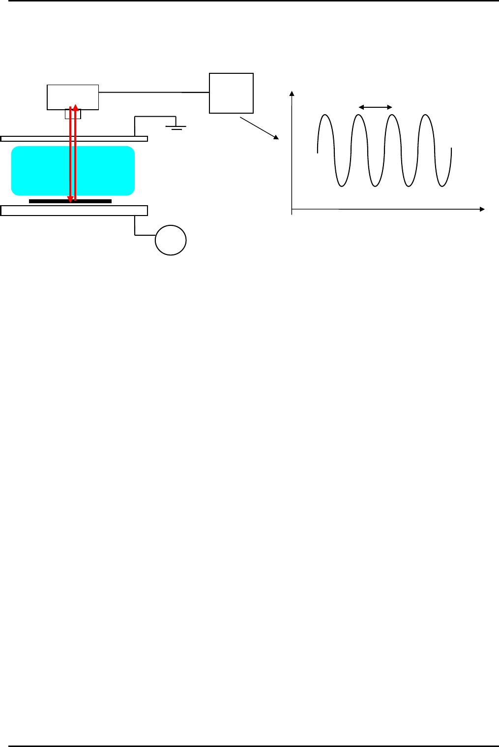
PKOKNMKO= i~ëÉê=áåíÉêÑÉêçãÉíêó=
RF
Process Chamber
Laser
Camera
Signal
Tim
e
PC
Process chamber
• In-situ etch rate monitoring
• Endpoint does not require etch stop layer
• Endpoint can be chosen anywhere within the layer once etch rate has been established.
PKOKNMKP= `çãé~êáëçå=çÑ=lbp=~åÇ=ä~ëÉê=ÉåÇéçáåí=íÉÅÜåáèìÉë=
A laser interferometer (LI) endpoint system has the benefits that it gives very precise measurement of etch
depth in the etched layer or layers and can be used on very small pieces of wafer.
It works best with a flat transparent layer (or stack of layers) on a reflective substrate.
It can be used to determine when the etch reaches an interface between differing materials (by detecting
a change in slope of the laser reflectance signal with time), or can measure the etch depth when partially
etching through a layer (by counting interference ripples).
It can also often be used to identify multiple interfaces when etching through different layers in a multi-
layer stack of materials (through the changes in reflectance of the materials in question).
The disadvantage is that the laser spot needs to be aligned every time to a suitable measurement point
on the wafer (i.e. an etched area, not a masked area). Also, it only measures a single point, so any process
non-uniformity will result in a range of etch depths across-wafer or across batch.
The optical emission spectroscopy (OES) system has the benefit that it does not require alignment for
every run, it simply looks at optical emission from the whole plasma. This however, means that it needs
larger wafers or a larger etched area (>2cm
2
) to effectively determine endpoint. The size of the etched
area needed for good OE endpoint is also dependent on the materials being etched since the emission
lines for certain materials can be very faint. Also, if the etch rate of the material is low then the
concentration of its etch species will be low.
OE can only detect a change in the strength of a particular emission line (or group of emission lines), so
can only detect when the etch passes through an interface between differing materials.
OE can give a qualitative idea of uniformity, since the length of the transition of the signal from before
endpoint to after endpoint will indicate the quality of the etch uniformity. Also the endpoint is more
accurate for the whole (average) of the wafer rather than a single point on the wafer.
Process Information (Information contained in this document is confidential)
Printed: 08 January 2006 09:37 Page 15 of 30 Issue 1: December 03
mä~ëã~ä~Ä= lñÑçêÇ=fåëíêìãÉåíë=mä~ëã~=qÉÅÜåçäçÖó= System Manual
PKOKNMKQ= =qóéáÅ~ä=lbp=ÉåÇéçáåí=ï~îÉäÉåÖíÜë=
Material etched Gas species
detected
Wavelength
nm
Rise/fall at endpoint
Si F 704 Rise
Si SiF 440, 777 Fall
Si SiCl 287 Fall
SiO2 F 704 Rise
SiO2 CO 483 Fall
Resist, polyimide O 843 Rise
Resist, polyimide CO 483 Fall
Resist, polyimide OH 309 Fall
Resist, polyimide H 656 Fall
Si3N4 N2 337 Fall
Si3N4 CN 387 Fall
Si3N4 N 674 Fall
W F 704 Rise
Al Al 391, 394, 396 Fall
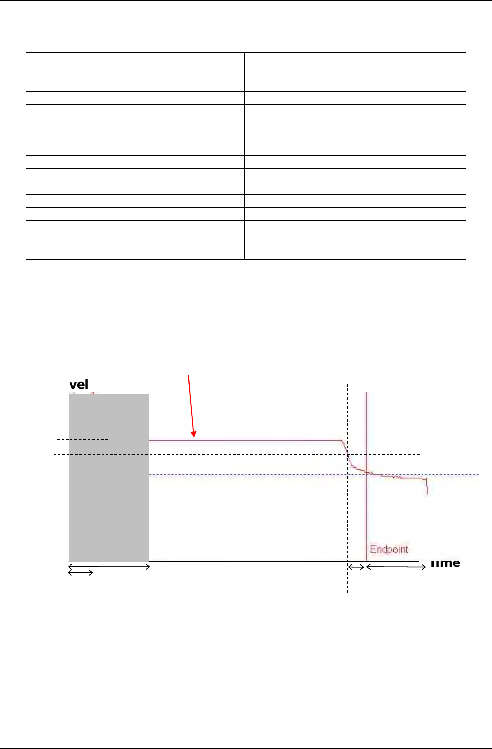
PKOKNMKR= båÇéçáåí=~äÖçêáíÜã=Éñ~ãéäÉë=
Signal
Time
% level
Normalisation
time
Endpoint
closed time
(no false
endpoint can
be found)
Endpoint
capture
time
Signal crosses its
endpoint threshold level.
Endpoint capture timer
started.
END of
process
Overetch
time
Endpoint trace – (signal, falling)
Normalisation
level
Threshold
level
Time
% level
Signal
Normalisation
time
Endpoint
closed time
(no false
endpoint can
be found)
Endpoint
capture
time
Signal crosses its
endpoint threshold level.
Endpoint capture timer
started.
END of
process
Overetch
time
Endpoint trace – (signal, falling)
Normalisation
level
Threshold
level
Process Information (Information contained in this document is confidential)
Issue 1: December 03 Page 16 of 30 Printed: 08 January 2006 09:37
System Manual= lñÑçêÇ=fåëíêìãÉåíë=mä~ëã~=qÉÅÜåçäçÖó= mä~ëã~ä~Ä
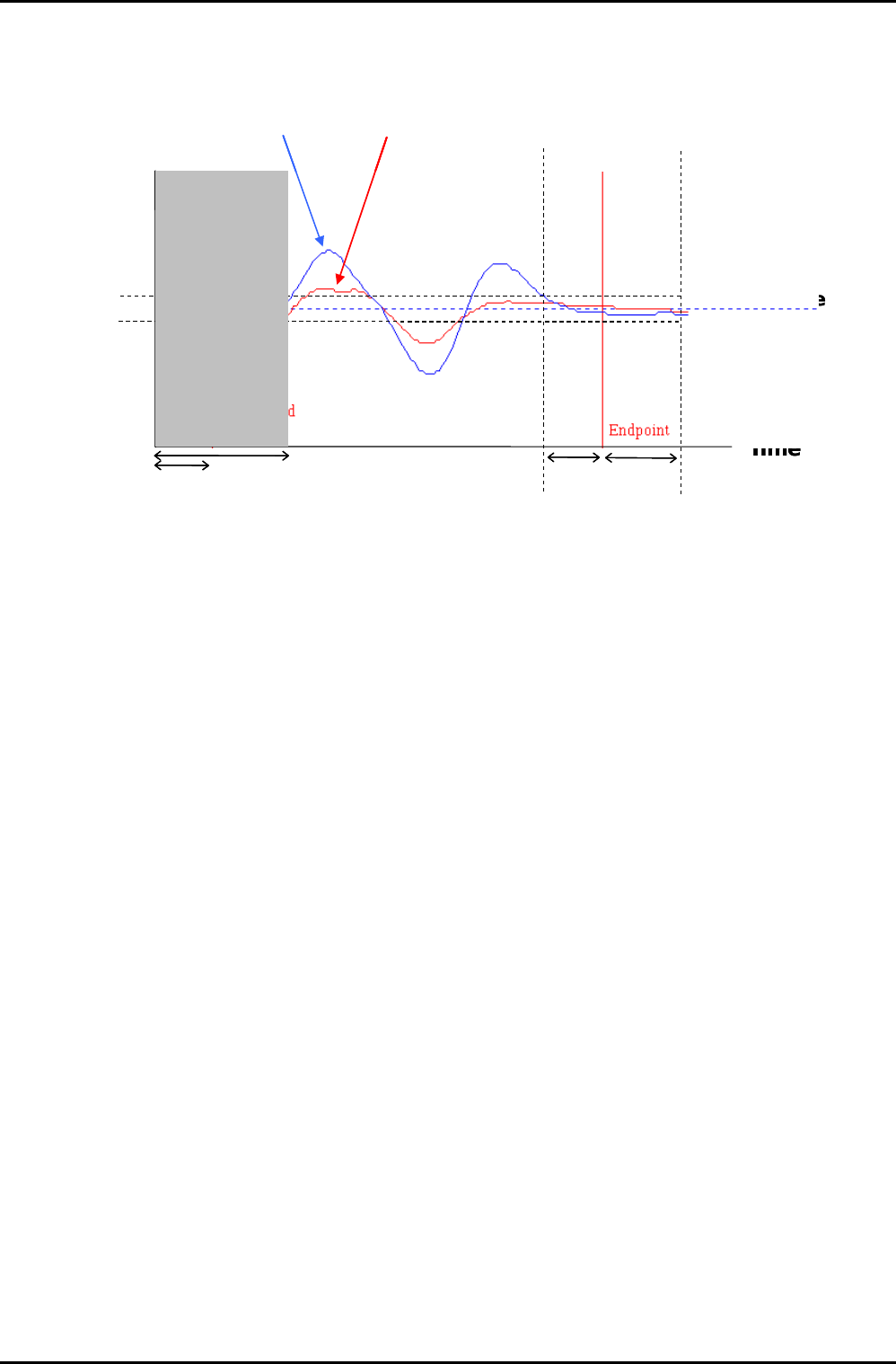
Signal
Time
% level
Derivative
zero line
Derivative
+/- derivative
threshold
Normalisation
time
Endpoint
closed time
(no false
endpoint can
be found)
Endpoint
capture
time
Derivative crosses its
endpoint threshold level.
Endpoint capture timer
started.
END of
process
Overetch
time
Endpoint trace – (derivative, less than)
Time
% level
Derivative
zero line
Signal
Derivative
+/- derivative
threshold
Normalisation
time
Endpoint
closed time
(no false
endpoint can
be found)
Endpoint
capture
time
Derivative crosses its
endpoint threshold level.
Endpoint capture timer
started.
END of
process
Overetch
time
Time
% level
Derivative
zero line
Signal
Derivative
+/- derivative
threshold
Normalisation
time
Endpoint
closed time
(no false
endpoint can
be found)
Endpoint
capture
time
Derivative crosses its
endpoint threshold level.
Endpoint capture timer
started.
END of
process
Overetch
time
Endpoint trace – (derivative, less than)
PKOKNN= d~ë=Å~äáÄê~íáçå=Ñ~Åíçêë=
See the MKS OEM manual for details of gas correction factors. However, it is worth pointing out that for
certain gases (e.g. H2 or He) it is recommended that the MFC is calibrated for that particular gas, since
they have very different gas properties compared to other gases, and hence the errors on calibrations
factors is large.
PKOKNO= bñÜ~ìëí=Éãáëëáçåë=
The gas emitted by a plasma etch process will be mostly made up of the input gases. However, there will
be a small but significant component of etch or plasma by-products (say up to ~10% in an RIE tool,
possibly more for ICP). The exact amounts will depend on process type and conditions. These can be any
combination of etch gas material and etched material.
For example:
Si + CF
4
= SiFx, CFx, F etc
SiO
2
+ CHF
3
= SiFx, COx, CFx, F, HF, CHx, SiOFx etc
Resist + O
2
= COx, O etc
As many of these by-products are toxic, it is a minimum requirement that these gases are exhausted in an
enclosed extraction system to the roof of the building - following health and safety regulations. In
addition to this, depending on local regulations, it may be necessary to have some form of gas scrubbing
before releasing these materials to the atmosphere.
Even if we were not running gases through the system, we would recommend that the system exhaust is
extracted correctly, since the pump exhaust will contain small droplets of pump oil which are in
themselves harmful to lung function.
Another important consideration is the gas absorbed in the pump oil. Since the exhaust gases contain HF
there will be a build up of HF in the pump oil. Therefore, it is important to use the correct protective
equipment when servicing the pump or changing pump oil, i.e. suitable gloves, protective clothing,
filtered facemask or breathing apparatus.
It is also worth remembering that when using O
2
processes the pump oil should be Fomblin oil and NOT
mineral oil to avoid risk of fire or explosive reaction between O
2
and mineral oil.
Process Information (Information contained in this document is confidential)
Printed: 08 January 2006 09:37 Page 17 of 30 Issue 1: December 03