EUS0153210_YFact_Standard_E.pdf - 第171页
3-51 3 Board Editor 4. Multi Lane Suppor t Additional features supporting the dual lane machine are listed below . 4.1 Board data select dialog is extended "Lane 1 Board Name", "Lane 1 Board Comment",…
3-50
3
Board Editor
n
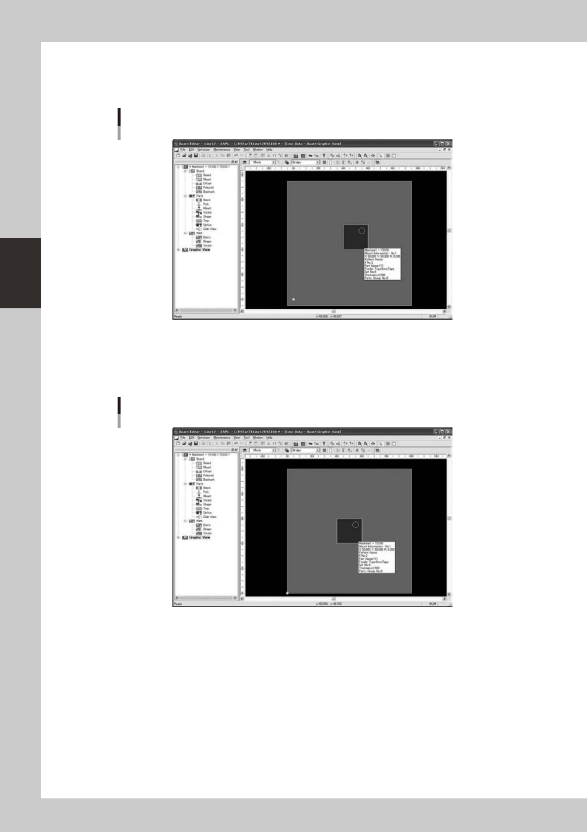
Examples of changing Offset value
The following figure is a graphic view that makes the offset value (5mm, 5mm).
The larger part is located at the center of board and parts are located at the origin position.
Offset (5mm, 5mm)
64377-S0-10
It is shown to be arranged at the position of (5mm, 5mm) while selecting parts at the starting point position
when seen from the substrate coordinates.
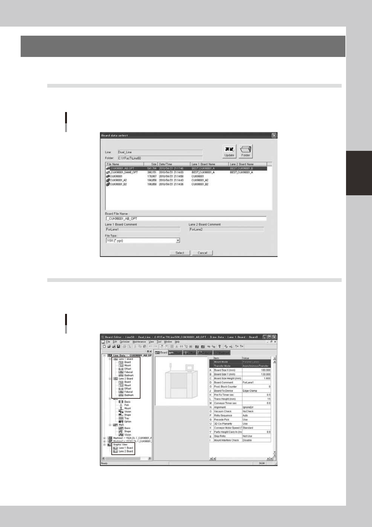
The following figure is a graphic view that makes the offset value (0mm, 0mm).
The coordinates are different though parts are arranged at the center of the substrate similarly.
Offset (0mm, 0mm)
64378-S0-10
Moreover, parts at the starting point position are arranged in (0,0) on the substrate.
3-51
3
Board Editor
4. Multi Lane Support
Additional features supporting the dual lane machine are listed below.
4.1 Board data select dialog is extended
"Lane 1 Board Name", "Lane 1 Board Comment", "Lane 2 Board Name", "Lane 2 Board Comment" are added.
On the line without dual lane machine, the former dialog is displayed.
Board data select dialog
64380-S0-00
4.2 The tree view is extended
Laneinformationisdisplayedinthetreeview.WhenreadingYGX(Combined)boarddata,[Lane1Board],
[Lane2Board]aredisplayedbelowtheboarddataandgraphicviewicon,andwhenselected,theinformation
for each lane is displayed in the main view.
Tree view
64381-S0-00
3-52
3
Board Editor
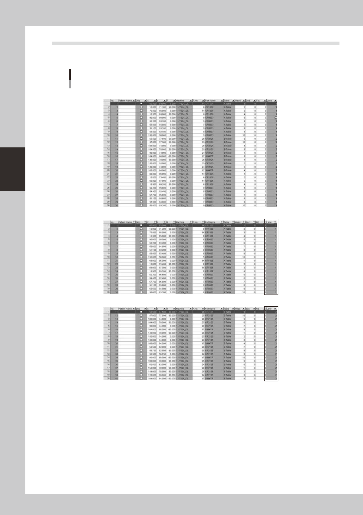
4.3 "Lane" column is added on "Mount" information
It shows which lane each mount data.on YGX(Combined) board data, when mount information for each lane is
opened,[Mount]columnisfilteredbyselectedlane.
“Lane” column is added
“Original Data”
Mount information of “Lane 1 Board” is selected
Mount information of “Lane 2 Board” is selected
64382-S0-00