YG12_英文保养手册.pdf - 第46页
2-4 2 Daily maintenance items 1.2 Checking the nozzles visually Use either of the following two methods to c heck the nozzle tip visually . n Remove the nozzle and check with a magnifying glass or similar tool. Nozzle ti…
2-3
2
Daily maintenance items
n
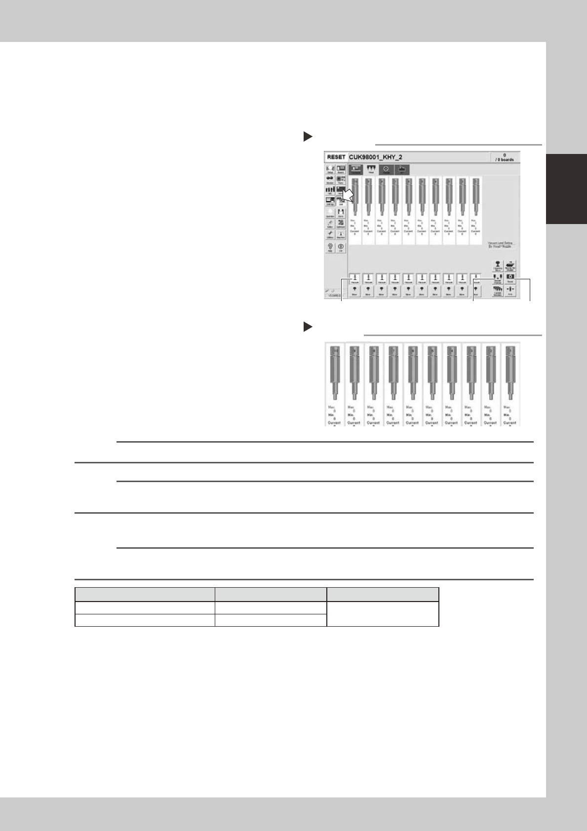
How to check for clogged nozzles (on the [Unit]-[Head] tab screen)
The term "clogged nozzle" used here indicates that material such as solder is adhering to the nozzle hole,
causing a rise in negative pressure even if no component is being picked up by the nozzle. This state might
cause problems such as component mounting errors. Check for clogged nozzles with the following procedure,
which is described using Type 302A nozzles as an example.
e
1
Attach the nozzle.
Press the emergency stop button and attach
Type 302A nozzles to all heads. When the
machine has a nozzle station, press the
[Nozzle Change] button to change the
nozzles.
54204-L5-00
2
Reset the numerical figure.
Open the [Unit] - [Head] tab screen. Then
press the [Reset] button on the lower right of
the screen to reset the pickup level values.
3
Generate negative pressure.
On the [Unit] - [Head] tab screen, set the
[Vacuum] buttons for all heads to ON. When
this value starts rising, wait 5 to 10 seconds
and set to OFF.
4
Check the vacuum levels.
Read the "Max" value shown in red on the
[Head] tab screen. If this value is 110 or less
then it is in normal range. If higher than 110,
then the nozzle hole might be dirty and
probably needs cleaning.
54205-L5-00
n
NOTE
The above example is for Type 302A nozzles so the values shown will be different for other types of nozzles.
n
NOTE
If a correct value cannot be obtained after cleaning even after performing steps 1 to 4, then the interior of the spline
shaft might be dirty. To check it, refer to the table on the right.
n
Vacuum level in spline shaft air path
n
NOTE
The vacuum level in the spline shaft air path might sometimes differ slightly depending on the air source and operating
conditions.Usetheabovecriteriavaluesforreferenceduringmaintenance.
Nozzle Typical criteria when open Typical criteria when sealed
Type 303A 85
190 or higher
No nozzle 70
Negative pressure generation
Step 1 to 3
[Nozzle Change] button[Vacuum] button [Reset] button
Negative pressure check
Step 4
2-4
2
Daily maintenance items
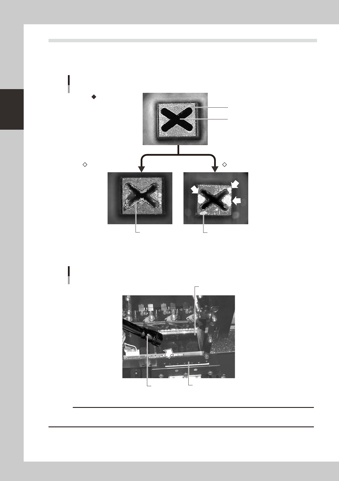
1.2 Checking the nozzles visually
Use either of the following two methods to check the nozzle tip visually.
n
Remove the nozzle and check with a magnifying glass or similar tool.
Nozzle tip
Solder is adhering to nozzle hole
Solder is adhering to nozzle tip
Nozzle hole
Nozzle state
Normal condition
Clogged nozzle Shiny material on tip
53201-L5-00
n
Leave the nozzle installed and check with a hand mirror and flashlight.
Flashlight
Multi-vision camera
Hand mirror
Check with a hand mirror.
53202-L5-00
c
If the above check reveals a dirty or a clogged nozzle, promptly clean the nozzle by referring to section 1.1 "Checking
and cleaning the nozzles", in Chapter 3.
2-5
2
Daily maintenance items
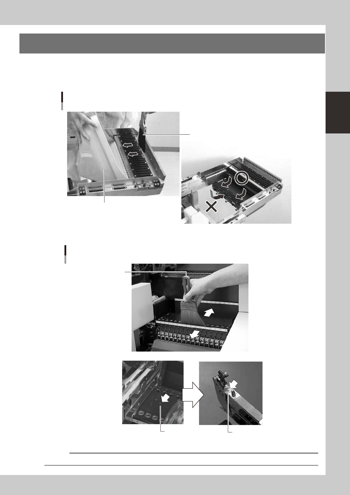
2. Cleaning the feeder plate
Clean the feeder plate by using the brush supplied with the machine. Chips or foreign matter falling on
the feeder plate might bite into the surface during feeder setting and cause the pickup position to deviate.
Periodic inspection and cleaning are recommended to prevent this problem.
n
YS12
Cleaning brush
Cleaning the feeder plate (bank)
Dustpan
53205-L5-10
n
YG12
Chips
Chips adhering to the bottom
of a tape feeder
Cleaning brush
Cleaning the feeder plate
53206-L5-00
Reference
You can clean chips and debris on the feeder plate while dropping them into the holes in the rear of the feeder plate.